Introduction
Extrusion Operator Guide
Plastics Materials, Processing, Troubleshooting, Drying, Purging, and Other Practical Information — authored by Daniel Stephens
Plastics is a sophisticated and diverse discipline. To excel, you need a good grasp of a wide range of concepts and data. The purpose of this guide is to provide extrusion operators with information that can help them to process, document, and troubleshoot more effectively.
While Routsis Training hopes you find this information useful, it should not be considered a substitute for continuous education. Techniques and technologies are advancing rapidly throughout the industry, which is why top-performing professionals turn to Routsis Training to keep enhancing their skills.
We invite you to further explore the topics covered in this guide through the comprehensive array of online training programs we provide at www.traininteractive.com.
Disclaimer
This reference guide contains general recommendations intended solely for informational use within the plastics extrusion industry. It is not intended to serve as engineering advice.
The information contained herein is based on published information, knowledge, research, and experience which are presumed to be accurate and complete to the best of our ability. All information is based on averaged data of commonly available grades of plastics and current industry practices at the time of this printing. Therefore, it is the user’s responsibility to review and confirm all design, calculations, and processing decisions.
You should always design and process using the recommendations that are provided by your raw material supplier, resin distributer, machine and equipment supplier(s).
Each material, machine, and process have their own set of influencing factors and, therefore, may or may not comply with the information provided in this guide. Routsis Training, LLC will not accept responsibility or liability for use of the information contained within this guide.
Contact Us
Routsis Training, LLC
379 Amherst Street PMB 233
Nashua, NH 03063 (USA)
phone:(978) 957-0700
website:www.traininteractive.com
store:store.traininteractive.com
email: info@traininteractive.com
Understanding Plastics
General Classification of Polymers
In the industry, plastics are often referred to as polymers, and the actual plastic pellets are commonly referred to as resin or raw material. A polymer is classified using different criteria and is considered to be either; natural or synthetic, thermoset or thermoplastic, and amorphous or semi-crystalline. Natural polymers are those found in nature, such as rubber, cotton, and silk. Plastics processing typically calls for the use of man-made synthetic polymers such as polyethylene, ABS, and nylon.
Thermoplastics vs. Thermosets
Polymers get their strength from a process called polymerization. During polymerization, small molecules called monomers combine to form long polymer chains. Thermosets are polymerized during processing while thermoplastics are polymerized before being processed. During processing, the polymer chains in thermosets fuse together, or cross-link. Once these polymers cross-link, they undergo a chemical change which prevents them from being melted and reprocessed. An egg is an example of a natural polymer which thermosets. Once the egg is heated, it solidifies and cannot be melted again.
Thermoplastics are long polymer chains that are fully polymerized when shipped by the resin manufacturer. Thermoplastics can be re-ground, melted and re-processed while retaining most of their original properties. An example of a natural thermoplastic material is wax. It can be melted and formed. Once cooled, the hardened wax can be melted and formed again. Unlike thermosets, most plastics companies prefer thermoplastic materials because they can be reprocessed and recycled.
Amorphous vs. Semi-Crystalline
Thermoplastic polymers can be categorized into two types; amorphous and semi-crystalline. Amorphous polymers melt gradually when heated. During cooling, amorphous polymer chains solidify slowly in a random orientation. By the end of the cooling phase, they shrink about 0.5%. Common amorphous polymers include ABS, polystyrene, polycarbonate, and PVC.
Semi-crystalline polymers melt quickly, once heated to their melting temperature. The rapidly melting polymer is easy to process compared to amorphous polymers. As a semi-crystalline material cools, portions of the polymer chains remain in a random state – while Semi-crystalline polymers melt quickly, once heated to their melting temperature. During cooling, semi-crystalline polymers shrink up to 3% — much more than amorphous polymers. Semi-crystalline polymers include acetal, nylon, polyester, polyethylene, and polypropylene.
Hygroscopic vs. Non-Hygroscopic
Thermoplastic polymers processed in the plastics industry are either hygroscopic; meaning they absorb moisture from the air, or non-hygroscopic; meaning they do not tend to absorb moisture from the air. Many low-cost commodity polymers, such as polypropylene, polyethylene, and polystyrene are non-hygroscopic polymers, which do not absorb moisture from the air. Any non-hygroscopic polymer can still get wet when exposed to water, or attract surface moisture in high humidity environments – such as outdoor silos, storage tanks, and overseas shipping containers.
Most engineering and specialty resins such as nylon, acetal, and polycarbonate are hygroscopic polymers, which absorb moisture from the air. These polymers have a natural attraction between the resin and water molecules. This creates a chemical bond, causing the polymer to retain water when it is exposed to moisture. In most cases, hygroscopic polymers require air which is both heated and dried to ensure proper material drying.
Hydrolysis is the breakdown of a water molecule when heated. Once broken down into hydrogen and hydroxide, these molecules will chemically react with the polymer chains, causing them to break. Visual defects such as splay, poor surface finish, bubbles, or delamination can occur as a result of moisture in hygroscopic polymers. Hydrolysis can also cause a significant change in the physical properties of the polymer including: reduced strength, increased brittleness, dimensional stability, poor heat resistance, and tendency to warp.
Viscosity
Viscosity is a measure of a material’s resistance to flow. A higher viscosity indicates a greater resistance to flow. Oil, for example, has greater viscosity than water. Typically, polymers with lower viscosity have low molecular weights. These materials are easier to process, but typically have less mechanical strength than a similar polymer having a higher melt viscosity.
Polymers are generally available in different grades, and each grade has particular flow characteristics. The viscosity of the polymer can be used to compare the flow characteristics of different polymers, or different grades of the same polymer. Viscosity data can also be used to qualify new materials by comparing a newer lot of material to a previously used material. Two of the most common methods of determining viscosity are Capillary Rheometry and Melt Flow Indexing.
Capillary Rheometry
Capillary Rheometry is an accurate method of measuring polymer viscosity. The polymer is usually tested at various temperatures and shear rates. When graphed, this data provides an accurate representation of the material’s processing behavior.
When comparing capillary rheometry data, try to compare the data at similar shear rates and temperatures. Although capillary rheometry data is preferred when comparing material flow characteristics, the testing process is time consuming. For this reason, capillary rheometry data is not readily available for all materials.
Melt Flow Index
Melt Flow Indexing is the most popular and least accurate method of determining material viscosity. This data is available for most materials and can be obtained from your material supplier.
The value obtained through the melt flow index test is a single data point, and tests the material at only one shear stress and one temperature. However, Melt flow index information from different materials and material grades may be used for a rough comparison of flow characteristics.
Plastic Materials Overview
Table of Plastic Material Properties
| Name | Grade | Spec. Grav. | Shrink % | D‑Temp °F (°C) | D‑Time (h) | Process °F (°C) |
|---|---|---|---|---|---|---|
| Acetal | Acetal | 1.39‑1.42 | 1.8‑2.2 | 175‑220 (80‑105) |
2‑3 | 370‑440 (190‑225) |
| Acrylic | PMMA | 1.08‑1.20 | 0.2‑0.6 | 150‑200 (65‑90) |
3‑6 | 350‑500 (175‑260) |
| Acrylonitrile Butadiene Styrene | ABS | 1.02‑1.05 | 0.4‑0.8 | 170‑200 (75‑95) |
2‑4 | 425‑500 (220‑260) |
| Chlorinated Polyvinylchloride | CPVC | 1.20‑1.30 | 0.5‑2.5 | 160‑180 (70‑80) |
1‑2 | 375‑435 (190‑225) |
| High Density Polyethylene | HDPE | 0.95‑0.96 | 1.5‑4.5 | 140‑160 (60‑70) |
1‑2 | 380‑550 (195‑290) |
| High Impact Polystyrene | HIPS | 1.04‑1.06 | 0.4‑0.8 | N/A | N/A | 410‑500 (210‑260) |
| Ionomer | Ionomer | 0.94‑0.98 | 0.4‑0.8 | 140‑175 (60‑80) |
2‑4 | 420‑530 (215‑275) |
| Linear Low Density Polyethylene | LLDPE | 0.91‑0.93 | 1.5‑4.5 | N/A | N/A | 325‑550 (165‑290) |
| Low Density Polyethylene | LDPE | 0.91‑0.93 | 1.5‑4.5 | N/A | N/A | 325‑550 (165‑290) |
| Nylon‑11 | Nylon‑11 | 1.04‑1.05 | 1.0‑2.0 | 150‑200 (65‑95) |
3‑4 | 440‑550 (225‑285) |
| Nylon‑12 | Nylon‑12 | 0.97‑1.06 | 0.6‑1.6 | 160‑200 (70‑95) |
3‑10 | 450‑570 (230‑300) |
| Nylon‑12/12 | Nylon‑12/12 | 1.06‑1.08 | 1.0‑1.5 | 160‑220 (70‑105) |
2‑4 | 500‑580 (260‑305) |
| Nylon‑4/6 | Nylon‑4/6 | 1.18‑1.21 | 1.6‑2.0 | 180‑220 (80‑105) |
2‑4 | 580‑600 (305‑315) |
| Nylon‑6 | Nylon‑6 | 1.10‑1.14 | 0.8‑1.5 | 150‑200 (65‑95) |
2‑6 | 460‑520 (240‑270) |
| Nylon‑6/10 | Nylon‑6/10 | 1.07‑1.08 | 1.0‑2.0 | 160‑200 (70‑95) |
2‑4 | 480‑550 (250‑290) |
| Nylon‑6/12 | Nylon‑6/12 | 1.03‑1.08 | 1.0‑1.5 | 150‑200 (65‑95) |
2‑4 | 450‑550 (230‑290) |
| Nylon‑6/6 | Nylon‑6/6 | 1.09‑1.14 | 1.0‑2.0 | 160‑220 (70‑105) |
2‑4 | 500‑580 (260‑305) |
| PC‑ABS Alloy | PC‑ABS | 1.10‑1.14 | 0.4‑0.8 | 180‑220 (80‑105) |
3‑5 | 480‑540 (250‑280) |
| PC‑PET Alloy | PC‑PET | 1.20‑1.22 | 0.6‑1.0 | 190‑230 (90‑110) |
3‑5 | 490‑550 (255‑290) |
| PC‑Polyester Alloy | PC‑Polyester | 1.18‑1.22 | 0.4‑1.0 | 190‑240 (90‑115) |
3‑5 | 480‑550 (250‑290) |
| Polyaryletherketone | PAEK | 1.37‑1.50 | 1.2‑1.6 | 300‑320 (150‑160) |
2‑10 | 700‑800 (370‑425) |
| Polybutylene Terephthalate | PBT | 1.30‑1.34 | 0.6‑2.0 | 200‑280 (95‑140) |
2‑5 | 450‑500 (230‑260) |
| Polycarbonate | PC | 1.15‑1.21 | 0.5‑0.8 | 240‑260 (115‑125) |
3‑5 | 500‑620 (260‑325) |
| Polyester | Polyester | 1.36‑1.40 | 1.5‑2.0 | 200‑270 (95‑130) |
3‑4 | 450‑510 (230‑265) |
| Polyetheretherketone | PEEK | 1.37‑1.50 | 1.0‑2.0 | 290‑310 (145‑155) |
2‑10 | 660‑750 (350‑400) |
| Polyetherimide | PEI | 1.27‑1.36 | 0.4‑0.7 | 250‑300 (120‑150) |
4‑6 | 640‑800 (340‑425) |
| Polyethersulfone | PES | 1.37‑1.50 | 0.8‑1.0 | 260‑300 (125‑150) |
2‑10 | 640‑730 (340‑385) |
| Polyethylene Terepthalate | PET | 1.25‑1.40 | 0.2‑0.5 | 250‑325 (120‑160) |
3‑6 | 480‑580 (250‑305) |
| Polyethylene Terepthalate Glycol | PETG | 1.25‑1.40 | 0.2‑0.5 | 150‑175 (65‑80) |
3‑6 | 300‑500 (150‑260) |
| Polyphenylene Oxide | PPO | 1.05‑1.10 | 0.5‑0.7 | 190‑240 (90‑115) |
2‑4 | 490‑590 (255‑310) |
| Polyphenylene Sulfide | PPS | 1.34‑1.40 | 1.0‑1.2 | 250‑320 (120‑160) |
2‑4 | 580‑640 (305‑340) |
| Polypropylene | PP | 0.89‑0.92 | 1.0‑2.0 | N/A | N/A | 390‑510 (200‑265) |
| Polystyrene | PS | 1.04‑1.06 | 0.3‑0.7 | N/A | N/A | 350‑525 (175‑275) |
| Polysulfone | PSU | 1.23‑1.25 | 0.4‑0.8 | 250‑300 (120‑150) |
4‑16 | 625‑725 (330‑385) |
| Polyurethane | PUR | 1.18‑1.20 | 0.4‑0.8 | 180‑280 (80‑140) |
4‑12 | 425‑525 (220‑275) |
| Polyvinylchoride | PVC | 1.20‑1.34 | 0.5‑2.5 | 160‑180 (70‑80) |
1‑2 | 330‑400 (165‑205) |
| Styrene Acrylonitrile | SAN | 1.07‑1.11 | 0.3‑0.7 | 160‑180 (70‑80) |
1‑2 | 420‑500 (215‑260) |
| Thermoplastic Elastomer | TPE | 0.90‑1.15 | 0.5‑2.0 | 150‑200 (65‑95) |
2‑4 | 350‑450 (175‑230) |
| Thermoplastic Elastomer Polyolefin | TPO | 0.91‑1.10 | 0.8‑2.0 | N/A | N/A | 375‑500 (190‑260) |
General Information About Common Materials
ABS (Acrylonitrile Butadiene Styrene)
| Trade Names | ABEL, ASTALAC, AVP, CEVIAN, CYCOLAC, ESPREE, EXCELLOY, KRALASTIC, LUSTRAN, Nyloy, Toyolac, TRILAC, Veroplas |
| General Characteristics | ABS is an amorphous terpolymer that consists of Acrylonitrile, Butadiene, and Styrene. This polymer has good flame retardant properties, a glossy finish, and high impact resistance depending on the blend. ABS has limited weathering resistance and certain grades have a relatively high cost. |
| Applications | General purpose, automotive, housings, electrical, and thin walled parts |
| Processing Temp. Range | 425-500 °F (220-260 °C) |
Acetal or POM (Polyoxymethylene)
| Trade Names | Celcon, Delrin, Hostaform, Kepital, Lucel, Lucet, RTP, Tarnoform, Tenac, Ultraform |
| General Characteristics | A highly crystalline polymer with good creep, fatigue, solvent, and water resistance. POM is a high strength and stiff polymer with good electrical properties. |
| Applications | Gears, bearings, automotive, and industrial |
| Processing Temp. Range | 375-420 °F (190-215 °C) |
Acrylic or PMMA (Polymethyl Methacrylate)
| Trade Names | Acrylite, Acryrex, Cyrex, Cyrolite, Kamax, Lustran, Optix, Plexiglas |
| General Characteristics | PMMA is a transparent amorphous thermoplastic low cost alternative to Polycarbonate when physical strength is not needed. This material also has better environmental stability than PS or PE, making it popular for many outdoor and automotive applications. |
| Applications | Automotive, TV Screens, Furniture, Windows, Medical |
| Processing Temp. Range | 350-500°F (175-260°C) |
CPVC (Chlorinated Polyvinylchloride)
| Trade Names | Harvel, Corzan, CTS, BlazeMaster, TempRite, Geon, Kaneka |
| General Characteristics | CPVC is an amorphous thermoplastic that is difficult to process due to very high shear sensitivity. Many grades of CPVC exist with different chlorine concentrations that effect the properties of the material. C PVC has strong chemical resistance with better temperature resistance than PVC. |
| Applications | Wire coating, tubing, automotive, electronics, profiles, drainage, and general purpose |
| Processing Temp. Range | 375-435°F (190-225°C) |
HDPE (High Density Polyethylene)
| Trade Names | Alathon, Bapolene, Braskem, Formolene, Ineos, SCLAIR |
| General Characteristics | HDPE is a highly crystalline opaque polymer with low moisture absorption as well as high tensile strength, chemical resistance and impact resistance. HDPE can also be machined and processed easily. |
| Applications | Automotive, coatings, containers, film, general purpose, industrial, packaging, tanks, and wire jacking |
| Processing Temp. Range | 380-550 °F (195-290 °C) |
HIPS (High Impact Polystyrene)
| Trade Names | ASTALAC, Avantra, CERTENE, Edistir, ESPREE, POLYREX, STYRON |
| General Characteristics | HIPS is an amorphous copolymer of Polystyrene and Polybutadiene rubber which has better impact resistance and dimensional stability than GPPS but lacks the superb clarity. HIPS has good machinability and dimensional stability with a low cost. As with GPPS, HIPS has poor solvent and electrical resistance. |
| Applications | Prototypes, housings, covers, toys, and appliances |
| Processing Temp. Range | 410-500 °F (210-260 °C) |
Ionomer
| Trade Names | Bexloy, Surlyn |
| General Characteristics | Ionomers are comprised of neutral and ionized polymer segments. Ionomers typically have ethylene based performance characteristics but with the added benefits of low temperature impact, chemical, and abrasion resistance. Some grades are designed to have high gloss and barrier properties. |
| Applications | Packaging, coatings, industrial, film, liners, sheet, and automotive exteriors |
| Processing Temp. Range | 420-530 °F (215-275 °C) |
LDPE (Low Density Polyethylene)
| Trade Names | Braskem, Kemcor, Lutene, Marlex, Riblene |
| General Characteristics | LDPE is a low cost, semi-crystalline polymer with good moisture resistance and flexibility. LDPE is generally used in high volume extrusion processes. |
| Applications | Agricultural, bags, coatings, containers, film, general purpose, packaging, and electrical insulation |
| Processing Temp. Range | 325-550 °F (165-290 °C) |
LLDPE (Linear Low Density Polyethylene)
| Trade Names | Braskem, CERTENE, DOW, Flexirene, NEO-ZEX, Petrothene, ULTZEX |
| General Characteristics | LLDPE is a semi-crystalline polymer with good moisture and chemical resistance. LLDPE typically has a rather high melt flow rate and exhibits good low temperature toughness and gloss. |
| Applications | Caps, containers, medical, toys |
| Processing Temp. Range | 325-550 °F (165-290 °C) |
PA-11 (Nylon-11)
| Trade Names | ASHLENE, Rilsan |
| General Characteristics | PA-11 is a semi-crystalline polyamide with outstanding thermal, chemical, and mechanical properties. PA-11 is a versatile polymer used in demanding situations due to its good impact properties and a high working temperature. |
| Applications | Hoses, electrical/electronics, automotive, sports, and medical |
| Processing Temp. Range | 440-550 °F (225-285 °C) |
PA-12 (Nylon-12)
| Trade Names | ASHLENE, Ecomass, Fostalon, Grilamid, PLUSTEK, Rilsan, Vestamid |
| General Characteristics | PA-12 is a semi-crystalline polyamide with great dimensional stability, impact strength, and chemical resistance. PA-12 is an excellent material for many applications because of its dimensional stability and properties at low temperatures. |
| Applications | Appliance components, automotive, bushings, cell phones, gears, general purpose, household goods, housings, medical, outdoor, engineering parts, sporting goods, tools, and wheels |
| Processing Temp. Range | 450-570 °F (230-300 °C) |
PA-4/6 (Nylon-4/6)
| Trade Names | Stanyl |
| General Characteristics | PA-4/6 is a semi-crystalline polyamide with outstanding structural performance properties and dimensional stability at elevated temperatures. PA-4/6 has excellent resistance to friction and wear with good flow properties. Many grades have some sort of fiber reinforcement to enhance the mechanical properties of the material. |
| Applications | Gears, automotive, electronics, and industrial |
| Processing Temp. Range | 580-600 °F (305-315 °C) |
PA-6 (Nylon-6)
| Trade Names | ALTECH, CAPRON, Durethan, Grilon, HiFill, Maxamid, Nypel, Radilon, Ultramid |
| General Characteristics | PA-6 is a semi-crystalline polyamide with great toughness and elasticity which makes it suitable for textile and oriented fibers. PA-6 also has high tensile strength and chemical resistance. |
| Applications | Textiles, fibers, zip fasteners, gears, gun frames, instrument strings, and surgical sutures |
| Processing Temp. Range | 460-520 °F (240-270 °C) |
PA-6/10 (Nylon-6/10)
| Trade Names | ALAMID, Nylene |
| General Characteristics | PA-6/10 is a semi-crystalline polyamide with a lower brittleness temperature, strength, and water absorption than other PA-6’s. PA-6/10 has good resistance to most solvents and diluted mineral acids. PA-6/10 tends to have large amount of shrinkage. |
| Applications | Electrical, filaments, and precision parts |
| Processing Temp. Range | 480-550 °F (250-290 °C) |
PA-6/12 (Nylon-6/12)
| Trade Names | ASHLENE, Nycal, Radici, Vestamid, Zytel |
| General Characteristics | PA-6/12 is a semi-crystalline polyamide with low water absorption compared to other nylons. PA-6/12 has more consistent properties than PA-6 when exposed to humidity and has good heat resistance and dimensional stability. |
| Applications | Electrical components, gears, general purpose, knife handles, gun frames |
| Processing Temp. Range | 450-550 °F (230-290 °C) |
PA-6/6 (Nylon-6/6)
| Trade Names | Celstran, Clariant Nylon 6/6, Elastoblend, HiFill, Nylene, Nymax, Polifil, Vydyne |
| General Characteristics | PA-6/6 is a semi-crystalline polyamide with good toughness and abrasion resistance. Typically used for commercial applications that will encounter extended use and abrasion. |
| Applications | Commercial grade fabrics, airbags, tires, textiles, carpets |
| Processing Temp. Range | 500-580 °F (260-305 °C) |
PAEK (Polyaryletherketone)
| Trade Names | Avaspire |
| General Characteristics | PAEK is a high performance semi-crystalline engineering thermoplastic that has extremely high temperature stability, mechanical strength, and chemical resistance. PAEK has slightly better dimensional stability and fatigue resistance than PEEK. |
| Applications | Chemical processing, electronics, medical, automotive, seals, valves, gears, and bearings |
| Processing Temp. Range | 700-800 °F (370-425 °C) |
PBT (Polybutylene Terephthalate)
| Trade Names | ABEL, ALCOM, ALTECH, ASHLENE, CELANEX, Crastin, Lutrel, PLANAC, POCAN, RAMSTER, Ultradur, VALOX, Vestodur |
| General Characteristics | PBT is a semi-crystalline polyester with good stiffness and toughness. PBT has similar properties to some nylons but with much less water absorption. PBT has a continuous service temperature of around 120°C and is often used as an electrical insulator. |
| Applications | Automotive, industrial, electronics, housings, medical |
| Processing Temp. Range | 450-500 °F (230-260 °C) |
PC (Polycarbonate)
| Trade Names | ALCOM, Apec, ASHLENE, CALIBRE, Carbotex, Durolon, Enviroplas, Hylex, LEXAN, Lupoy, Makrolon, Panlite, RAMTOUGH, TRIREX |
| General Characteristics | PC is an amorphous polymer with great impact resistance and optical clarity along with good heat resistance, toughness, and dimensional stability. Many polycarbonate products have surface coatings since PC does not have good chemical or scratch resistance. |
| Applications | Exterior automotive components, engineering components, housings, lenses, structural parts, medical components, and bullet proof sheeting |
| Processing Temp. Range | 500-620 °F (260-325 °C) |
PC/ABS (PC/ABS Alloy)
| Trade Names | Abel PC/ABS, ASTALOY, Bayblend, CYCLOY, Duroloy, EMERGE, EXCELLOY, Hybrid, Lupoy, Multilon, Novalloy-S, TECHNIACE, TRILOY, Verolloy, WONDERLOY |
| General Characteristics | PC/ABS is an amorphous thermoplastic copolymer of Polycarbonate and Acrylonitrile Butadiene Styrene. PC/ABS offers the properties of both PC and ABS including: the strength and heat resistance of PC and the flexibility of ABS. PC/ABS exhibits high toughness even at cold temperatures. |
| Applications | Automotive, electronics, medical, and aeronautical |
| Processing Temp. Range | 480-540 °F (250-280 °C) |
PC/PET (PC/PET Alloy)
| Trade Names | Makroblend, XENOY |
| General Characteristics | PC/PET is an amorphous thermoplastic blend that combines the properties of both PC and PET. It can be opaque or transparent and has high rigidity, dimensional stability, and impact resistance. |
| Applications | Sporting goods, electrical/electronic, automotive, industrial/mechanical, and household |
| Processing Temp. Range | 490-550 °F (255-290 °C) |
PEEK (Polyetheretherketone)
| Trade Names | Arlon, Ketaspire, MOTIS, PEEK-OPTIMA, VESTAKEEP, VICTREX |
| General Characteristics | PEEK is a high performance semi-crystalline engineering thermoplastic that has extremely high temperature stability and mechanical strength. PEEK has great dimensional stability, fatigue resistance, and chemical resistance with low smoke and toxic gas emission when exposed to flame. |
| Applications | Piston parts, gears, aerospace, automotive, chemical processing, and insulation |
| Processing Temp. Range | 660-750 °F (350-400 °C) |
PEI (Polyetherimide)
| Trade Names | ULTEM |
| General Characteristics | PEI is an amorphous polymer with excellent dimensional stability, chemical resistance, mechanical strength, and high temperature performance. PEI is electrically conductive which makes it suitable for some electronics applications. |
| Applications | Medical devices, microwave cookware, insulators, automotive, electrical/electronics, and metal replacement |
| Processing Temp. Range | 640-800 °F (340-425 °C) |
PES (Polyethersulfone)
| Trade Names | HiFill PES, Ratron, SUMIKAEXCEL, TRIBOCOMP, Ultrason |
| General Characteristics | PES is an amorphous transparent polymer with good stiffness and heat resistance. PES is suitable for high continuous use temperatures over extended periods of time. PES has high rigidity and dimensional stability over a broad temperature range. PES is susceptible to UV degradation and weathering. |
| Applications | Medical, automotive, industrial, pistons, filters/membranes, and electrical/electronics |
| Processing Temp. Range | 640-730 °F (340-385 °C) |
PET (Polyethylene Terepthalate)
| Trade Names | Ultrason, Valox, Hiloy, Impet, Petra, Shulandur, Ektar, Rynite, Selar, Dacron, Terylene |
| General Characteristics | PET is a semi-crystalline thermoplastic that is commonly used for synthetic polyester fibers and plastic bottle production. Most bottle manufacturers control the clarity of PET by limiting the degree of semi-crystallinity since higher levels of semi-crystallinity cause the product to turn opaque. PET has excellent chemical resistance and can withstand temperatures in excess of 212°F (100°C). |
| Applications | Bottles, fibers, synthetic fabrics, films, and packaging |
| Processing Temp. Range | 480-580°F (250-305°C) |
PETG (Polyethylene Terepthalate Glycol)
| Trade Names | Spectar, Vivak, Eastar |
| General Characteristics | PETG is an amomrphous thermoplastic which has similar properties to PET but with better mechanical and dimensional stability. PETG also has greater clarity and impact resistance than PET which makes it very popular for packaging applications such as thermoforming. |
| Applications | Fibers, films, and packaging |
| Processing Temp. Range | 300-500°F (150-260°C) |
PP (Polypropylene)
| Trade Names | Braskem, CERTENE, COPYLENE, Exelene, FERREX, Formolene, GAPEX, Hostacom, INEOS, Maxxam, Polifil, POLYFLAM, Pro-fax, RAMOFIN, TIPPLEN, YUPLENE |
| General Characteristics | PP is a versatile semi-crystalline polymer with high impact resistance and melt flow rates. PP is a resilient polymer that acts as a living hinge when cyclically loaded or fatigued. PP is difficult to bond with adhesives and has poor low temperature impact strength. |
| Applications | Automotive, films, containers, industrial applications, general purpose, and living hinge applications |
| Processing Temp. Range | 390-510 °F (200-265 °C) |
PPO (Polyphenylene Oxide)
| Trade Names | Fiberfil, Noryl |
| General Characteristics | PPO is an amorphous engineering plastic with high temperature resistance, dimensional stability, and electrical resistance along with low thermal expansion. PPO is sensitive to organic solvents and is susceptible to environmental stress cracking. |
| Applications | Pumps, valves, fittings, electrical components, manifolds, covers, housings, and coatings |
| Processing Temp. Range | 490-590 °F (255-310 °C) |
PS (Polystyrene)
| Trade Names | Amoco, Bapolan, Eporex, Styron, Valtra |
| General Characteristics | PS is an inexpensive amorphous polymer with great optical clarity. Unfilled polystyrene is typically called GPPS (general purpose polystyrene) and is rigid but brittle. PS can be used in virtually all processes, making it extremely versatile in the marketplace. PS has poor thermal stability and solvent resistance. |
| Applications | Toys, packaging, sheet, housings, appliances, household goods, and expanded beads |
| Processing Temp. Range | 350-525 °F (175-275 °C) |
PVC (Polyvinylchloride)
| Trade Names | APEX, Geon, Georgia Gulf, Manner, Reinier, Roscom, Sylvin, Unichem |
| General Characteristics | PVC is an amorphous thermoplastic that is difficult to process as a homopolymer. Many grades of PVC exist with different plasticizer concentrations that effect the processing of the material. Rigid PVC has strong chemical resistance and moderate temperature resistance. PVC has poor UV resistance. |
| Applications | Wire coating, tubing, automotive, electronics, profiles, general purpose, and medical |
| Processing Temp. Range | 330-400 °F (165-205 °C) |
SAN (Styrene Acrylonitrile)
| Trade Names | FORMPOLY, KIBISAN, Kumho, LG SAN, Lustran, Porene, SANREX, Veroplas |
| General Characteristics | SAN is an amorphous copolymer of styrene and acrylonitrile. SAN has higher strength, rigidity, and chemical resistance than polystyrene but lacks the same optical clarity. SAN has poor impact strength and low thermal capabilities. |
| Applications | Electrical, appliances, cosmetics, medical, containers, and automotive |
| Processing Temp. Range | 420-500 °F (215-260 °C) |
TPC-ET (Thermoplastic Copolyester Elastomers)
| Trade Names | Arnitel, Elitel, Hytrel, Keyflex, Riteflex |
| General Characteristics | TPC-ET polymers are amorphous thermoplastic copolymers that exhibit the flexibility of rubbers and the strength and processability of thermoplastics. TPC-ET blends have excellent flex fatigue resistance and a broad use temperature. They have good toughness and resist hydrocarbons. |
| Applications | Adhesives, cast film, coatings, filaments, hose, sheet, and tubing |
| Processing Temp. Range | 490-550 °F (255-290 °C) |
TPE (Thermoplastic Elastomer)
| Trade Names | Ecdel, Estamid, Estane, Hytrel, Kraton, Ontex |
| General Characteristics | A TPE is an amorphous copolymer of thermoplastic and elastomeric monomers and properties. TPEs can come in many classes including block-copolymers, polyolefin blends, and thermoplastic polyurethanes to name a few. Generally, these polymers have high heat resistance and ozone resistance. |
| Applications | Gaskets, automotive, sporting goods, tubing, and medical |
| Processing Temp. Range | 350-450 °F (175-230 °C) |
TPO (Thermoplastic Polyolefin)
| Trade Names | Exxtral, Lupol |
| General Characteristics | A TPO is a polymer/filler blend consisting of some fraction of polyolefin(s) and reinforcements. They have good dimensional stability and usually have a balance between stiffness and impact resistance in semi-structural and non-structural applications. |
| Applications | Appliances, automotive, electrical, consumer, packaging, and nonwovens |
| Processing Temp. Range | 375-500 °F (190-260 °C) |
PPS (Polyphenylene Sulfide)
| Trade Names | Fortron, Ryton, Sultron, TEDUR, Thermec, Xtel |
| General Characteristics | PPS is a semi-crystalline polymer which usually contains fillers or reinforcements. PPS has excellent ionizing radiation and chemical resistance. PPS is self-extinguishing and has low toxicity smoke when exposed to flame. |
| Applications | Chemical pumps, electrical components, coatings, piping, rods, and seals |
| Processing Temp. Range | 580-640 °F (305-340 °C) |
PSU (Polysulfone)
| Trade Names | Udel, Ultrason |
| General Characteristics | PSU is an amorphous polymer with good stiffness and heat resistance. PSU is transparent and maintains good mechanical properties over a wide temperature range. PSU has one of the highest service temperatures of melt-processable thermoplastics which can be autoclaved and steam sterilized without any loss in physical integrity. |
| Applications | Medical, electrical/electronics, filters, industrial, and aerospace |
| Processing Temp. Range | 625-725 °F (330-385°C) |
PUR (Polyurethane)
| Trade Names | Chronothane, Hydrothane, Polyblend |
| General Characteristics | PURs are a large family of polymers that may be thermoset or thermoplastic polymers with a broad array of properties. PUR has high abrasion resistance and is typically used as a coating, foam, or elastomer copolymer. These polymers tend to be weak to UV rays and most organic solvents. |
| Applications | Adhesives, bushings, coatings, insulation, piping, sealants, sheet, washers, and wheels |
| Processing Temp. Range | 425-525 °F (220-275 °C) |
Material Properties & Additives
Common Fillers and Fibers
Fillers and fibers are generally added to plastic materials to increase mechanical, chemical, or electrical properties as well as to reduce material costs in some cases. Reinforcing fibers such as carbon or glass are used to enhance mechanical properties while talc and clay are used as fillers.
Common Fillers and Fibers
Alumina |
Calcium Carbonate |
Carbon Black |
Clay |
Glass Bubbles |
Glass Fibers |
Graphite |
Quartz |
Talc |
Molydenum Disulfide |
Wollastonite Silicate |
|
|---|---|---|---|---|---|---|---|---|---|---|---|
| ABS | • | • | • | ||||||||
| Acetal | • | ||||||||||
| Acrylic | • | ||||||||||
| Nylon | • | • | • | • | • | • | • | ||||
| Polycarbonate | • | ||||||||||
| Polyester TP | • | ||||||||||
| Polyethylene | • | • | • | • | • | • | |||||
| Polypropylene | • | • | • | • | • | • | |||||
| Polystyrene | • | • | • | • | • | ||||||
| Polysulfone | • | ||||||||||
| Polyurethane | • | • | • | • | • | • | |||||
| PPO Modified | • | ||||||||||
| PVC (Rigid) | • | • | • | • | • | • | • | • | • |
Effect of Glass Fibers on Mechanical Properties
| ASTM D792 | ASTM D995 | ASTM D638 | ASTM D790 | ASTM D648 | ASTM D696 | |
|---|---|---|---|---|---|---|
| Specific Gravity | Shrink % | Tensile Strength kPsi (Mpa) |
Flexural Modulus kPsi (Mpa) |
Deflection Temp. 264 Psi (1.8MPa) °F (°C) |
Thermal Expansion % per °F (% per °C) |
|
| ABS | 1.05 | 0.6 | 6 (41) | 320 (2200) | 195 (91) | 0.0053 (0.0095) |
| 30% Glass | 1.28 | 0.1 | 14.5 (210) | 1100 (7600) | 220 (104) | 0.0016 (0.0029) |
| Acetal | 1.42 | 2.0 | 8.8 (60) | 400 (2800) | 230 (110) | 0.0045 (0.0081) |
| 30% Glass | 1.63 | 0.3 | 19.5 (134) | 1400 (9600) | 325 (163) | 0.0022 (0.0040) |
| Nylon 6 | 1.14 | 1.6 | 11.8 (81) | 400 (2800) | 167 (75) | 0.0046 (0.0083) |
| 30% Glass | 1.37 | 0.4 | 23 (158) | 1200 (8300) | 420 (216) | 0.0017 (0.0031) |
| Nylon 6/6 | 1.14 | 1.8 | 11.6 (80) | 410 (170) | 170 (77) | 0.0045 (0.0081) |
| 30% Glass | 1.37 | 0.4 | 26 (180) | 1300 (9000) | 490 (254) | 0.0018 (0.0032) |
| PPO | 1.06 | 0.5 | 9.5 (65) | 360 (2500) | 265 (129) | 0.0033 (0.0059) |
| 30% Glass | 1.27 | 0.2 | 21 (144) | 1300 (9000) | 310 (154) | 0.0014 (0.0025) |
| Polycarbonate | 1.2 | 0.6 | 9 (62) | 330 (2300) | 265 (129) | 0.0037 (0.0067) |
| 30% Glass | 1.43 | 0.1 | 18.5 (127) | 1200 (8300) | 300 (149) | 0.0013 (0.0023) |
| Polyester T.P. | 1.31 | 2.0 | 8.5 (59) | 340 (2300) | 130 (54) | 0.0053 (0.0095) |
| 30% Glass | 1.52 | 0.3. | 19.5 (134) | 1400 (9600) | 430 (221) | 0.0012 (0.0022) |
| HDPE | 0.95 | 2.0 | 2.6 (18) | 200 (1400) | 120 (49) | 0.0060 (0.0108) |
| 30% Glass | 1.17 | 0.3 | 10 (69) | 900 (6200) | 260 (127) | 0.0027 (0.0049) |
| Polypropylene | 0.91 | 1.8 | 4.9 (34) | 180 (1200) | 135 (57) | 0.0040 (0.0072) |
| 30% Glass | 1.13 | 0.4 | 9.8 (68) | 800 (5500) | 295 (146) | 0.0020 (0.0036) |
| Polystyrene | 1.07 | 0.4 | 7 (48) | 450 (3100) | 180 (82) | 0.0036 (0.0065) |
| 30% Glass | 1.28 | 0.1 | 13.5 (93) | 1300 (9000) | 215 (102) | 0.0019 (0.0034) |
| Polysulfone | 1.24 | 0.7 | 10 (69) | 400 (2800) | 340 (171) | 0.0031 (0.0056) |
| 30% Glass | 1.45 | 0.3 | 18 (124) | 1200 (8300) | 365 (185) | 0.0014 (0.0025) |
| SAN | 1.08 | 0.5 | 9.8 (68) | 500 (3400) | 200 (93) | 0.0034 (0.0061) |
| 30% Glass | 1.31 | 0.1 | 17.4 (120) | 1500 (10000) | 215 (102) | 0.0018 (0.0032) |
Heat Resistance
The safe continuous heat resistance temperature of plastics is an important factor in many applications. Although a polymer like PTFE has a high heat resistance temperature of 550°F it lacks most of its mechanical properties at that point. The following figure shows the continuous heat resistance temperatures of plastics but it does not necessarily mean the plastic will maintain optimal mechanical properties at that point.
Continuous Heat Resistant Temperature of Plastics
| °C | °F | |
|---|---|---|
| 316 | 600 | Most Plastic Materials Char or Burn |
| 302 | 575 | |
| 288 | 550 | PTFE |
| 274 | 525 | |
| 260 | 500 | Polyimide |
| 246 | 475 | |
| 232 | 450 | Phenolic Asbestos Filled |
| 218 | 425 | Silicone Mineral Filled |
| 204 | 400 | |
| 191 | 375 | PCTFE |
| 177 | 350 | |
| 163 | 325 | Polysulfone |
| 149 | 300 | Alkyds, Phenolics, Chlorinated Polyether |
| 135 | 275 | |
| 121 | 250 | Melamine, Nylon, Polypropylene, PPO, Polycarbonate |
| 107 | 225 | ABS/Polycarbonate Alloy |
| 93 | 200 | Acetal, ABS, Surlyn, Noryl, Polyurethane |
| 79 | 175 | Acrylics, Cellulosics, Polyethylene, Polystyrene, SAN, Vinyls |
| 66 | 150 | Urea |
| 52 | 125 | |
| 38 | 100 | |
| 24 | 75 | Room Temperature |
| 10 | 50 |
Hardness
The hardness of a plastic is usually recorded as a measure of the resistance of the material to indentation by a steel ball or point under load. The hardness is expressed as a number derived from the net increase in depth of the indentation during the hardness test. Since all plastics have unique characteristics, the observed hardness is a time dependent value which will change with the rate of loading.
Hardness of Common Plastic Materials
| Rockwell | Durometer | Barcol | ||
|---|---|---|---|---|
| M | R | Shore D | ||
| ABS | 85‑109 | |||
| Acetal | 94 | 120 | ||
| Acrylic | 85‑105 | 49 | ||
| Cellulosics | 30‑125 | |||
| PTFE | 50‑65 | |||
| PCTFE | 75‑95 | 76 | ||
| Ionomer | 60 | |||
| PPO | 78 | 119 | ||
| Nylon 66 | 108‑120 | |||
| Nylon 6 | 120 | |||
| Polycarbonate | 70 | 116 | ||
| Polyester Rigid | 65‑115 | 30‑50 | ||
| HDPE | 60‑70 | |||
| MDPE | 50‑60 | |||
| LDPE | 41‑46 | |||
| PP | 90‑110 | 75‑85 | ||
| GPPS | 68‑80 | |||
| Vinyl Rigid | 117 | 65‑85 | ||
| Vinyl Plasticized | 40‑100 Shore A |
|||
| Urea Cellulose | 110 | |||
| Silicone | 84 | |||
| Polysulfone | 69 | 120 | ||
| Polyester | 80 | |||
Burn Characteristics
Sometimes a plastic material is identified by its burn characteristics. The table below illustrates the various characteristics of plastics when ignited.
CAUTION: Any burn test should be done with the proper safety equipment and a ventilated hood.
Burn Characteristics of Plastics
| Material | Color | Odor | Speed |
|---|---|---|---|
| PE | Bright Blue Core | Paraffin | Fast |
| PP | Bright Blue Core | Acrid / Diesel fumes | Slow |
| PS | Yellow | Marigold | Fast |
| ABS | Yellow | Acrid | Slow |
| POM | Bluish | Formaldehyde | Slow |
| PA | Bluish | Burnt Hair | Slow |
| PC | Yellow | Phenol | Slow |
| CA | Greenish/ Yellow | Vinegar | Slow |
| PET | Yellow | Burnt Rubber | Fast |
| ABS/PC | Yellow | Acrid/Phenol | Slow |
| PVC-U | Greenish/ Yellow | Hydrochloric | Slow |
| PVC-P | Greenish/ Yellow | Hydrochloric | Slow |
Material Drying
Proper material handling and drying is critical to producing a consistent product with a reliable process.
Drying Terminology
Non-Hygroscopic Polymers
Many low-cost commodity polymers, such as polypropylene, polyethylene, and polystyrene are non-hygroscopic polymers, which do not absorb moisture from the air. Any non-hygroscopic polymer can still get wet when exposed to water, or attract surface moisture in high humidity environments — such as outdoor silos, storage tanks, and overseas shipping containers. Since water does not have a chemical bond to Non-Hygroscopic polymers, this moisture can easily be removed using forced hot air.
Hygroscopic Polymers
Resins such as nylon, acetal, and polycarbonate which absorb moisture from the air are called hygroscopic. These polymers have a natural attraction between the polymer and water molecules.
In most cases, hygroscopic polymers require air which is both heated and dried to ensure proper material drying. This air must have the moisture removed through a dehumidifying process, such as desiccant dryers or vacuum dryers.
Hydrolysis
Hydrolysis is the breakdown of a water molecule when heated. Once broken down into hydrogen and oxygen, these molecules will chemically react with the polymer chains, causing them to break. Visual defects such as splay, poor surface finish, bubbles, or delamination can occur as a result of moisture in Hygroscopic polymers.
Hydrolysis can also cause a significant change in the physical properties of the polymer including: reduced strength, increased brittleness, dimensional instability, poor heat resistance, and tendency to warp.
Relative Humidity
Humidity is a measure of how much moisture is present in the air. This is usually expressed as relative humidity, which is a percentage of how saturated with water the air is. For example, if the air is completely saturated and cannot hold any more water, it is represented as 100 percent humidity. The lower the air temperature, the less moisture air can hold.
Dewpoint
The point where the drop in air temperature results in 100% humidity is considered its dewpoint. This is the temperature where water will start to condense on most surfaces – including plastic pellets.
Therefore, a lower “dewpoint” value means the air is drier and will draw more moisture from the pellets.
Drying Procedures
Material drying specifications for hygroscopic materials are typically provided by the material supplier and are represented in both drying temperature and drying time. Additionally, your company may have specific drying temperatures and times that work best for certain grades of material.
The drying temperature refers to the temperature of the air being supplied from the dryer to the pellets. The drying time is typically provided as a range, such as 3 to 4 hours. This refers to the range of time the material can be exposed to the heated air provided by the dryer.
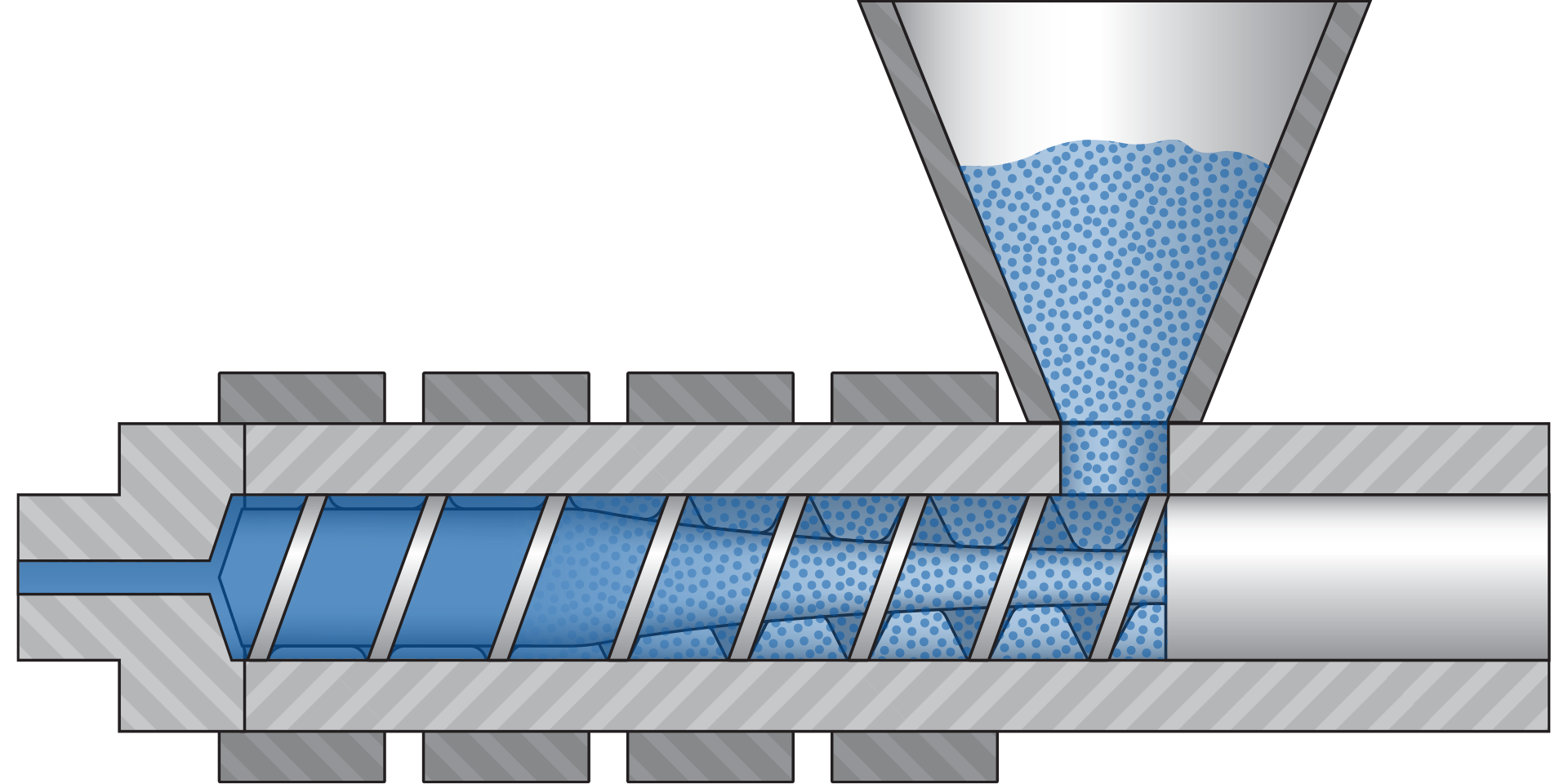
Comon Material Dryers
Material drying specifications for hygroscopic materials are typically provided by the material supplier and are represented in both drying temperature and drying time. Additionally, your company may have specific drying temperatures and times that work best for certain grades of material.
The drying temperature refers to the temperature of the air being supplied from the dryer to the pellets. The drying time is typically provided as a range, such as 3 to 4 hours. This refers to the range of time the material can be exposed to the heated air provided by the dryer.
Hot Air Dryer
The hot air dryer forces heated air though the pellets. These dryers heat the air using gas or electric heaters, and then force the hot air through the pellets using a blower fan. This method of drying is typically used to either remove surface moisture or preheat the polymer.
Compressed Air Dryer
The compressed air dryer uses air that is provided from an existing air compressor. The air passes through a heater before reaching the pellets.
At the compressor, the air loses moisture and the dewpoint typically drops 25 °C (45 °F) below the dewpoint of the ambient air within the room. This system typically takes 2 to 4 hours to completely dry and prepare a hygroscopic material for processing.
Desiccant Dryer
The desiccant dryer forces air that is both heated and dehumidified. The desiccant dryer uses a blower to draw cooled air from the hopper and forces the air through a moisture absorbing ‘desiccant bed’. After moisture is removed in the desiccant bed, the air is heated before reaching the pellets.
Since these dryers are capable of both heating and drying the air, they can significantly reduce the dewpoint. This dryer typically takes 2 to 4 hours to completely dry and prepare a hygroscopic material for processing.
Vacuum Dryer
The vacuum dryer functions on the same principle by which water boils. At typical atmospheric pressures, water will boil at 100 °C (212 °F).
The low pressures within vacuum dryers cause the water to boil at temperatures around 56 °C (133 °F), resulting in a faster drying time at lower temperatures. It is critical for each company to create its own material-specific procedures for vacuum drying.
PVC & CPVC Polymers
Definition of PVC
Polymers are large molecular chains made up of many smaller molecules. The word polymer can be broken up into two parts:
- Poly means “Many”
- Mer means ”Unit”
- Polymer means “Many Units”
A polymer consists of many smaller molecules called monomers. These monomers are combined into longer polymer chains. The process used to combine these molecules is called polymerization. In most cases, the longer the polymer chains, the tougher and stronger the polymer.
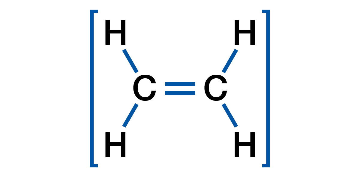
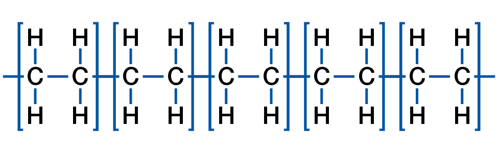
Polyethylene, for example, is one of the most commonly used polymers in the world. This polymer starts with an ethylene monomer of 2 carbons and 4 hydrogen atoms: When polymerized, Polyethylene is comprised of hundreds, thousands, or millions of repeating Ethylene units.
Smaller polyethylene chains (consisting of only hundreds of repeating units each) are often used for low strength applications, such as candle wax. Longer polymer chains make stronger polyethylene, which can be used for injection molding, extrusion, and blow molding processes.
Polyethylene, like all polymers, gets much of its strength from the entanglement of all these relatively long polymer chains. This strength is the highest when the polymer is cooled and the atoms are in a ‘low energy’ state where they are difficult to move around and untangle.
Ethylene Monomer
Polyethylene Polymer
PVC Polymer
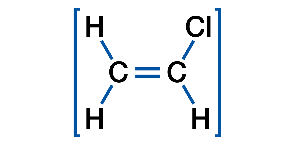
The Polyvinyl Chloride, or PVC, polymer starts with a monomer known as Vinyl Chloride. Vinyl Chloride is comprised of 2 Carbon, 3 Hydrogen, and 1 Chlorine atom.
When polymerized, the Vinyl Chloride monomer becomes the Polyvinyl Chloride polymer which is commonly known as PVC.
Vinyl Chloride Monomer
Polyvinyl Chloride Polymer
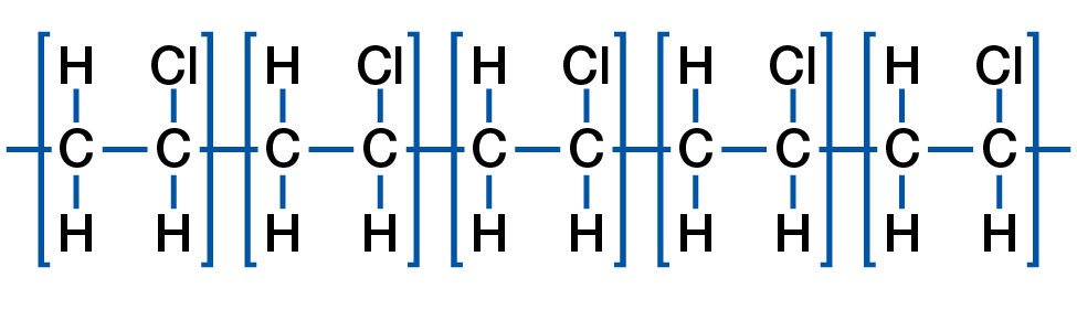
PVC gets very rigid when it cools, thus when these stiff PVC chains entangle, they gain a lot of strength. This chain entanglement contributes to much of PVC’s overall strength. The atoms on one polymer chain are also attracted to atoms on adjacent chains resulting in significant intermolecular attraction. The combination of rigid chains and intermolecular attraction cause the PVC polymer to be very hard and rigid. This rigidity makes PVC very difficult to process as the polymer chains will break if subjected to too much work and shear when melting or processing. Viscosity is a material’s resistance to flow, the higher the resistance to flow, the higher the viscosity. The rigidity of PVC causes the polymer to have a very high viscosity as compared to many other polymers.
The chlorine present on every unit of the PVC polymer chain causes material be less heat stable than most polymers during processing. When melt processing PVC, it is always important to avoid processing the material with too much heat or shear. When PVC degrades, one byproduct is chlorine gas, which is very dangerous and corrosive when not properly ventilated. The byproduct of degraded PVC will cause any PVC it comes in contact with to start degrading immediately. If excessive PVC degradation occurs, the result could be a cloud of chlorine gas or an explosion, both of which are very dangerous and potentially deadly. These gasses also contribute to the corrosion of metal surfaces such as the screw, barrel, die, and any exposed metal around the processing equipment.
When processed, PVC gives off a highly corrosive chlorine gas. This chlorine gas will accelerate rust, corrosion or oxidation on any surface it encounters including stainless steel. It is imperative that all exposed machinery and die surfaces are routinely cleaned, lubricated, or protected to prevent premature corrosion. There are also chlorine neutralizing sprays which can be used on the mold or die surfaces after processing PVC to reduce post-processing corrosion.
Chlorine and CPVC
PVC has good fire resistance, but the addition of chlorine to the PVC polymer chain will further increase the heat and fire resistance of the end product. Additional chlorine can be added through chlorination making a more rigid material known as Chlorinated Poly-Vinyl Chloride or CPVC. The extra chlorine increases chain rigidity and intermolecular attraction making the polymer very strong, rigid, and more difficult to process.
CPVC is challenging to process because it is much more rigid than PVC — with a much higher viscosity. CPVC is so rigid that it can be difficult to process without causing material degradation. For most of the remainder of this guide, PVC and CPVC will be used together as the concerns when processing the two materials are similar even though CPVC is more difficult to process.
Crosslinking of PVC or CPVC
The Vinyl Chloride monomer is turned into the PVC and CPVC polymer during polymerization. Most grades of PVC/CPVC will polymerize into long chain thermoplastic polymers.
Under the right conditions such as when degrading or when exposed to radiation, PVC and CPVC will cross-link. Crosslinked polymers are called thermoset polymers. These thermoset PVC/CPVC polymers are less common because they cannot be reground and re-processed. The remainder of this guide only focuses on the processing of Thermoplastic PVC/CPVC polymers and does not cover thermosets.
PVC & CPVC Components and Additives
Any additive, plasticizer, colorant, and heat stabilizer must be properly combined into a homogenous mix with the PVC or CPVC during processing or the material will not reach peak performance.
Fillers & Additives
Many different fillers and additives such as Talc, Calcium Carbonate, Sodium Sulfate, Glass Fibers, and colorants can be added for many reasons. Additives and fillers are introduced early in the polymer blending process. These could be added to reduce the cost of the material, increase the strength of the material, change the color, adjust the gloss, or even increase the density of the material.
Plasticizers
Due to the rigidity of PVC and CPVC, plasticizers are added during blending to help the polymer flow when processed. Large amounts of plasticizers are added when flexible PVC polymers are being blended. Plasticizers are usually comprised of smaller molecules which reduce the intermolecular entanglement or molecular attraction.
Rigid PVC and CPVC have a high viscosity because they use a minimal percentage of plasticizers to help flow, yet allow the final product to retain its stiffness. Rigid PVC and CPVC are commonly used for high strength applications such as plumbing pipes, pipe fittings, house siding, window frames, and control panels on ‘white goods’ such washing machines and dish washers.
Flexible PVC uses a much higher percentage of plasticizer to reduce the stiffness of the intended products. A further benefit of using a plasticizer is that it reduces the viscosity of the PVC. Common uses for flexible PVC are tubing, synthetic leather, shower curtains, films, and gaskets.
Heat Stabilizers
PVC and CPVC degrade very easily. Heat stabilizers are added during polymer blending to help reduce degradation and improve thermal stability when processing. The most common heat stabilizers are metal-based and often include multiple elements such as tin, barium, and calcium. These additives can withstand heat much better than PVC or CPVC alone, which improves thermal stability during processing.
PVC & CPVC Regrind
Thermoplastic polymers can be reground and re-processed, but PVC and CPVC can only be reprocessed until they degrade. When PVC or CPVC degrades, the degraded material will cause any PVC or CPVC molecules it encounters to degrade quickly due to a rapid chemical reaction. For this reason, you cannot put degraded PVC or CPVC back into the process or it will rapidly create more degraded PVC in the barrel and in your final product.
Since PVC and CPVC degrade easily, you must always be careful when processing regrind. Good quality PVC and CPVC regrind may have value as can be reprocessed. Good quality regrind refers to reground material which has no contamination or degradation.
Bad quality PVC or CPVC regrind has a negative value and will not only create more scrap in your process, but will also lead to more degraded PVC or CPVC. It is more cost effective to discard bad PVC or CPVC as processing degraded regrind material will lead to increased scrap and production losses. If your PVC or CPVC has degraded regrind in the mix, then it will create more degraded PVC in your final product. Degraded regrind or contamination will create a lower quality part which will likely have reduced properties such as poor strength, impact resistance, chemical resistance, and appearance. Processing degraded regrind will increase the chances that faulty product will reach your customers.
Performance vs. Non-Performance PVC & CPVC
Processing Performance PVC or CPVC
Performance PVC and performance CPVC refers to plastic used for functional applications such as pipes, fittings, siding, films, hoses, tubing, bottles, and window profiles. These products must meet specific performance requirements such as tensile, flexural, compressive, impact strength, and/or resistance to chemicals, UV, or radiation. The PVC or CPVC reaches peak performance when all the additives, plasticizers, heat stabilizers, etc. are thoroughly mixed which is a condition known as gelation or fusion.
Without proper gelation or fusion, the performance products may fail during use. It is common for performance products to meet all visual and dimensional requirements but fail when put through performance testing. This is often the result of inadequate gelation in the final product. Gelation and fusion will be covered in later sections of this guide, but general discussions related to Performance PVC/CPVC is covered below.
Performance polymers should be close to peak gelation or fusion at the end of the process to achieve the highest possible performance. When polymers reach peak gelation or fusion, the PVC or CPVC cannot accept much more time, temperature, or shear before the polymer begins to start degrading. For this reason, it is very difficult to process regrind made from performance PVCs. Regrind performance PVC or CPVC degrades easier than the virgin material in the pellet or powder forms because it has an additional time, temperature, and shear history. When regrind is incorporated in performance PVC and performance CPVC applications, the percentage used is often below 10% to prevent potential degraded material from causing significant performance losses. Waste material which does not show any signs of degradation such as burning, streaks, dieseling, or die lines is considered as usable regrind.
Documenting Performance PVC or CPVC
Essentially, the correct balance of time, temperature, and shear will help the PVC or CPVC fully mix and approach peak gelation or fusion. When the process makes acceptable product which meets all the visual and performance requirements, is it critical to fully document the process. This process documentation should include all the factors which go into making a good product. Specifics will be covered in later sections of this guide, but general documentation guidelines are covered below.
Machine, auxiliary, and downstream information should be recorded with any critical process information. Detailed process output data should be recorded as well as any information which helps identify what made good product during the specific production run. This includes the material lot, blending facility and equipment, pelletizing facility and line, percentage regrind, and any rheological information such as melt flow index, dryer residence time, barrel residence time, material temperature, coolant temperature, and any results from post-production testing including dimensional and gelation-related data.
Detailed process documentation should identify the factors which specifically relate to gelation or fusion such as all time, temperature, and shear factors. This way, the processor has information to help make process adjustments to compensate for time, temperature, and shear factors differences between one production run and another.
Proactive Process Adjustments
For performance PVC or CPVC applications, good process documentation allows the processor to make predictive adjustments based on an expected change in the time, temperature, and/or shear in an upcoming run. For example, if an upcoming production run is going to contain regrind, the barrel temperatures can be reduced to help mitigate the additional heat the regrind adds to the process. If a production run is scheduled to be run in a machine with a smaller barrel, the barrel temperatures or pressures might need to be increased to put more temperature or shear into the material – this can help compensate for the shorter time the PVC or CPVC will spend in the smaller barrel.
When using different equipment or material from run to run, a modified process may be necessary to get the same product performance. As a processor, you can control aspects of time, temperature, and shear on the PVC or CPVC, but many times it is the role of the processor to compensate for changes they cannot control such as a different machine or lot of material. The more a processor can predict these changes, the less scrap will be produced and the higher the production efficiency your process will have.
A proactive approach is important for performance PVC and CPVC applications. This is because most performance testing requires a specified time to pass such as 12 or 24 hours before the product can be properly tested. If a processor can gain some skill and experience in making effective proactive process adjustments, then it is often possible to run production while the product waits to be tested because there is a high-level of confidence that the product being produced will meet all quality parameters including performance testing.
Reactive Process Adjustments
The first use of this data is to make process adjustments on setting up, followed by adjustments after the product is found to be defective. If the PVC or CPVC shows degradation, then there needs to be a reduction in time, temperature, and/or shear such as a reduction in screw speed, barrel temperature, or a change to a machine with a smaller barrel. Conversely, if there is not enough gelation, then the time, temperature and/or shear applied to the material will need to be increased to get more gelation.
When using the same or similar processing equipment, the same process should be used to maintain the same balance of time, temperature, and shear. The part is likely to perform the same in testing, but good documentation will help you determine and compensate for differences during startup.
Keep in mind that many flexible PVC or CPVC applications can be considered performance PVC or performance CPVC applications if they must meet specific performance requirements such as chemical resistance or chemical characterization testing which require the PVC to be at near peak gelation or fusion to pass.
Non-Performance PVC Products
“Non-Performance” refers to non-functional applications such as decorative parts like panels, trim, and appliance panels. These products tend to have specific visual and fit requirements, but the PVC or CPVC does not have to perform at or near its peak strength or resistance capabilities.
These parts should always be processed with the minimal time, temperature, and shear necessary to make good product. This strategy provides the processor with a larger process window with the least likelihood of degrading the polymer. If the PVC or CPVC is processed at conditions significantly lower than necessary to achieve peak gelation, the defective products and waste can be reground and reprocessed with a lower risk of degradation.
As with Performance PVC and Performance CPVC applications, it is important to document all factors that make acceptable product, including all process outputs, material data, and time, temperature, and shear information. The positive aspect to non-performance PVC and non-performance CPVC is that you can usually match up the process outputs on similar processing equipment and the process should make good product. The detailed process documentation will help you identify and make efficient reactive adjustments when a significant change occurs in the time, temperature, and shear relationship such as degradation.
When using significantly different material grades and batches, or changing machinery from run to run, a proactive process adjustment should be considered before the process is started. This is recommended for non-performance PVC/CPVC applications to increase the efficiency of a production run. However, it is not typically as critical as it tends to be with performance PVC/CPVC products.
Time/Temperature/Shear Relationship for PVC & CPVC
Performance vs. Non-Performance
Performance PVC and Performance CPVC refers to polymers which must meet stringent strength or resistance properties. For the purpose of this guide, we will occasionally differentiate these polymers from non-performance PVC or non-performance CPVC polymers where the application may have specific appearance or dimensional requirements but does not have stringent performance requirements.
Gelation or Fusion
Once the polymer, additives, plasticizers, heat stabilizers, and other components in PVC or CPVC are fully mixed, the polymer is at peak strength. This is known as gelation or fusion because all of the components have become combined or fused into what is known as a gel. Full gelation or fusion refers to the point where the polymer matrix has fully formed, and it has achieved its optimal strength.
It is important to note that performance PVC/CPVC plastics are provided to the processor in a blended form, but all the components are not fully mixed when in pellet or powder form. This is because the process to properly combine all these elements puts excess heat and shear into the polymer. If this is all done before final processing, then the polymer will start to degrade once it is re-melted to processing temperatures. It is the job of the processor to complete the combining of the Rigid PVC or CPVC with the desired additives in the barrel. When done properly, the plastic in the final product has adequate gelation or fusion to achieve the desired properties.
Rigid PVC or CPVC products which have not reached full gelation or fusion will have reduced physical properties such as low impact, flexural, tensile, or compressive strength. These polymers which have low-strength will also have reduced resistance to attack from chemicals, UV rays, and electricity. Low gelation or fusion can cause product failures in the field such as bursting pipes, breaking fittings, cracked siding, leaking containers, or even food contamination.
The biggest problem the performance PVC or performance CPVC processor faces is when PVC or CPVC has not reached high gelation or fusion. In this instance, the plastic product may look good and meet the dimensional requirements and preliminary quality checks, but fail when the final product is tested for performance such as a pressure, strength, crush, flexural, impact, or chemical testing.
For performance PVC or CPVC to reach high gelation or fusion, a proper combination of time, temperature, and shear must be applied to the polymer. Gelation or fusion will not occur if there is too little time, temperature, or shear involved in processing. Unfortunately, when too much time, temperature, or shear is applied to the PVC or CPVC, it will begin to degrade. Good PVC and CPVC processing is based on understanding the proper balancing of time, temperature, and shear for your specific application.
In the Process Documentation portion of this guide, we’ll review how to document time, temperature, and shear on your process documentation.
Time
With respect to time, temperature, and shear for performance PVC or CPVC, time refers to the time the PVC or CPVC is exposed to heat and/or shear. To effectively combine all the polymer components and additives, both heat and shear must be applied over a period of time. Time examples include:
- Barrel Residence Time
How long the polymer remains in the barrel exposed to heat - Cycle Time
The time required to produce a fixed amount of product - Dryer Residence Time
How long the polymer remains in the dryer exposed to heat - Blending Time
How long the polymer is exposed to heat and shear during component blending
If any PVC or CPVC is exposed to heat or shear for an excessive amount of time, the polymer will begin to degrade. If performance PVC or CPVC is not exposed to heat or shear for enough time, insufficient gelation or fusion will occur, and the resulting product will not meet the end use requirements.
This time factor is very important to consider during production stoppages, slowdowns, shutdowns, startups, and changeovers as the polymer will begin to degrade. This is why it is very important to replace all the PVC with heat stable polymers immediately whenever the processing equipment is to be down or idle for any extended period of time.
Temperature
Temperature refers to the heat history applied to the PVC or CPVC. To effectively combine all the components, heat is a necessary factor. Without applying heat, the PVC and CPVC polymer chains would be too rigid to properly mix. Temperature examples include:
- Blender Temperature
- Barrel Zone Temperatures
- Die Temperatures
- Dryer Temperatures
- Coolant Temperatures
Temperature control is critical with PVC or CPVC. A temperature spike occurring anywhere during mixing, pelletization, drying, or processing can start the degradation process. To reduce heat generation, PVC or CPVC molding machines and extruders should use barrel heaters equipped with cooling fans. These fans circulate air around each barrel zone to prevent the material from overheating. In many instances, cored extruder screws cooled by air or oil mail may be used to help prevent overheating of the polymer during processing.
Shear
Shear refers to the work or mechanical energy applied to the PVC or CPVC. To effectively combine all the components, shear is a necessary factor as the polymer must be thoroughly mixed. Examples of when PVC or CPVC is sheared include:
- Material mixing and blending
- Pelletization
- Screw rotation and screw geometry, features and characteristics
- Back pressure in the extruder caused by the breaker plate, filters, die head, or die
- Material flow through the extruder, die, or mold
- Restrictions or blockages in the extruder, die, or mold
With PVC or CPVC, shear creates significant heat. Always be very careful whenever adding shear to a PVC or CPVC process. Adding both energy and heat can bring the material to the point of degradation very quickly.
PVC or CPVC Gelation or Fusion
The point where PVC or CPVC approaches peak mixing of components is called gelation or fusion. When gelation occurs, the PVC or CPVC polymer has the highest strength, impact resistance, chemical resistance, heat resistance, fire resistance, and UV resistance. Gelation is critical for high performance PVC or CPVC products such as pipes, fittings, containers, siding, window casings, and medical tubing.
Incomplete or non-gelation - Many parts look good after processing but have not reached gelation resulting in lower mechanical and resistance properties. In most cases where performance is critical, insufficient gelation or fusion will often result in parts failing during use.
Non-gelation is generally acceptable for applications such as appliance panels, decorative components, and other low-risk applications where fit and appearance is more important than performance.
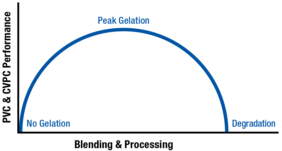
The figure below shows the starting state of polymer with the lowest strength at ‘No Gelation’. Once the polymer starts receiving a time, temperature, and shear history the strength of the polymer increases with corresponding increase in gelation or fusion. Once too much time, temperature, or shear is applied, the PVC or CPVC will start to degrade resulting in a loss in polymer properties the more it degrades.
PVC or CPVC Arc of Gelation or Fusion
PVC Degradation
Once a high level of gelation or fusion is achieved, additional time, temperature, or shear will begin the degradation process. Once PVC or CPVC begins to degrade, it undergoes a chain reaction which accelerates more degradation of adjacent PVC chains.
This degradation chain reaction is a primary reason why it’s critical that all PVC or CPVC processing equipment is streamlined: without any gaps or hang-up points where the polymer flow can stop. If the PVC or CPVC stagnates at any point, the stagnated polymer will degrade — in turn, causing all polymer that touches it to degrade.
This degradation is often seen in extrusion in situations where degraded PVC/CPVC is present inside or on the edge the extrusion die. This will cause a continuous brown stripe in the extrudate until the degraded material is removed from the die. Another example of this is degraded material in the nozzle of an injection molding machine. This degraded PVC or CPVC will cause brown streaks on the gate area of the molded parts on every cycle until the process is stopped and the nozzle is properly cleared of degraded material.
Excessive PVC degradation is very dangerous. As mentioned before, polymer chains degrade in a rapid, continuous reaction. Toxic chlorine gas can be produced rapidly and the polymer chains can crosslink and seize the screw inside the barrel. PVC or CPVC cannot be left in the barrel for any extended period of time. Rather, it must be replaced with a heat stable material, such as a Polyolefin (PE or PP) or Purging Compound.
Testing of Gelation or Fusion of PVC & CPVC
The only way to know the amount of gelation or fusion in your PVC or CPVC after being processed is to conduct a test on the material using one of the following tests. All the tests in this section apply to testing of the final product. In all cases, the final product testing is destructive, thus you will not be able to sell the product after gelation or fusion is tested.
Chemical Immersion Test
In this test, the PVC is immersed in a chemical for a pre-determined amount of time to visually evaluate the amount of damage the chemical does to the polymer. To conduct this test, the PVC or CPVC sample is cut at an angle to help expose a large amount of internal surface area to the chemical. The internal surface of the PVC must be exposed for this test to provide accurate results because the outer surfaces tend to develop a skin which may resist chemical attack.
For example, ASTM D2152-17 entitled ‘Standard Test Method for Adequacy of Fusion of Extruded Poly (Vinyl Chloride) (PVC) Pipe and Molded Fittings by Acetone Immersion’ uses product which is cut and submersed in acetone for a specified period of time.
If the processed PVC or CPVC have a high amount of gelation or fusion, the PVC or CPVC will show no signs of attack at the end of this chemical immersion test. This means the product has passed the test and is likely to have good strength and resistance properties due to a high degree of gelation or fusion.
If the PVC or CPVC sample shows discoloration, pitting, streaking, or any noticeable change in appearance, the polymer components have not been properly mixed, or some degradation has begun to occur. In either case, the polymer matrix does not have enough gelation or fusion.
The chemical immersion test is a common general test for gelation or fusion because poorly gelated PVC or CPVC will be easily attacked. This is because all the components have not been blended into a cohesive polymer matrix.
The challenge with this test is that the person evaluating the results must have the necessary experience to evaluate minor attacks on the PVC or CPVC. The results of this test are generally considered pass or fail, but an experienced technician can provide a subjective evaluation on the degree of attack and type of damage which has been done to the sample by the chemical.
Aside from Pass or Fail, the results of this test are not quantitative, but observational data can be helpful to the technician – for example, pitting in the tested sample might indicate poor mixing while streaking in the sample may indicate degraded polymer.
The general methodology of the chemical immersion test is straightforward:
- The test sample is prepared by cutting it with an angle to expose the internal polymer
- The area of the sample being tested is submerged into the chemical for a period of time
- The sample is removed and chemical is washed off to make the sample safe to handle
- The exposed polymer is visually inspected to determine whether the polymer passed or failed
Advantages & Disadvantages
There are several advantages and disadvantages associated with using the Chemical Immersion Test to evaluate the gelation or fusion of PVC and CPVC materials.
Advantages:
- Many chemicals are available for use in this test
- Testing is easy to perform
- Cost is low
Disadvantages:
- The test takes a significant amount of time to complete
- The chemicals used can be very dangerous
- Proper PPE and ventilation are required
- Evaluation requires training and experience
- Evaluation of results are very subjective
- Test results are not quantitative
Impact Strength Test
In this test, the PVC or CPVC is subjected to a high-speed impact of a specific weight moving at a specific speed which is measured as energy. In some tests, the sample breaks and the loss of energy is measured. In other tests, the sample is tested at a specific energy level to determine if it will break or not. This is a pass/fail test. With respect to PVC or CPVC, the better the part performs in testing, the more gelation is likely present in the product.
Pendulum Impact Strength Test
The most common form of impact strength test is the pendulum test. In this test, a weighted pendulum is swung through the test sample to break it. The pendulum starts on one side of the testing apparatus from a fixed point and the highest position of the pendulum’s upswing is measured. This measurement corresponds to the amount of energy lost as the pendulum passed through the sample. The less the pendulum swings afterward, the more energy has been lost during the breaking of the sample. In theory, properly gelated product will have a higher energy loss when being tested than low gelation product does.
Different tests may use different weights and methods for holding the sample. For example, ASTM D2560-10 titled ‘Standard Test Methods for Determining the Izod Pendulum Impact Resistance of Plastics’ uses a notched sample which is struck while clamped in a vertical orientation.
The general methodology of different pendulum impact testers is common:
- The test sample is prepared by cutting it to size and often is notched to reduce the effects of the outer polymer skin from skewing the test results
- The sample is secured in the testing apparatus
- The swinging weight is lifted and released from a fixed point
- The energy loss is measured
Falling Weight Impact Strength Test
The falling weight impact test is a simple way to test the impact resistance of a product. These tests use a weight with a piercing element which is dropped from a specific height. The test is designed to determine whether the product resists puncture in a pass or fail evaluation. The energy used in the test is created by the dropping of the weight in the test. In most cases, the product has a specific weight and height impact that it is designed to resist. When the test is designed properly, a well-produced and gelated PVC or CPVC product will pass this test by resisting puncture, while poorly manufactured product will fail the test. Different tests use different weights and points for puncturing the sample. In many applications, the final product is fixtured under the falling weight. This tests how a product will perform when impacted by something realistic such as a hammer.
Different tests may use different weights and methods for holding the sample. For example, ASTM D5420-21 titled ‘Standard Test Method for Impact Resistance of Flat, Rigid Plastic Specimen by Means of a Striker Impacted by a Falling Weight (Gardner Impact)’ offers different product geometries, weights, and heights for standardized testing.
The general methodology of falling weight impact testers is common:
- The test sample is prepared by cutting it to size (where applicable)
- The cut sample or finished device is secured in the testing apparatus
- The falling weight is lifted and released from a fixed height
- The sample either passes or fails the test based on whether the product is punctured
Advantages & Disadvantages
There are several advantages and disadvantages associated with using Impact Strength testing to evaluate the gelation or fusion of PVC and CPVC materials.
Advantages:
- Many testing systems are available
- The tests are relatively easy to perform
- Results are easy to evaluate
- Pendulum impact testing is quantitative
- Falling weight impact testing is easy to perform final product
Disadvantages:
- Apparatus used can be dangerous
- Poor results are not always caused by poor gelation or fusion
- Falling weight impact testing is not quantitative
- Extensive testing of good and bad product required to determine pass or fail criteria
Mechanical Strength Test
The purpose for using mechanical strength testing for performance PVC and CPVC is that high-performing product has adequate strength as a result of good processing and adequate gelation or fusion. With any mechanical strength testing, the overall strength of the product being tested can be heavily influenced by the process used to manufacture it. This means that a failure in strength testing could be indicative of a bad process and not necessarily inadequate gelation or fusion.
Since a good product is expected to pass strength testing requirements, this testing method is a good measure of overall product quality, which includes adequate gelation of the PVC or CPVC in the final product.
There are many mechanical testing methods used for testing, but the most common are:
- Tensile Strength (ASTM D638)
Tests resistance to being pulled apart - Compressive Strength (ASTM D695)
Tests resistance to being compressed or crushed - Flexural Strength (ASTM D790)
Tests resistance to being bent or flexed - Pressure Strength (ASTM D1785)
Tests resistance to bursting or leaking under pressure
When tested, the sample is subjected to either a steady strain and the stress and/or failure is measured, or the sample is tested at an increasing stress and the strain and/or failure is measured. In many cases, the strength of the final product can be tested with a properly designed testing apparatus – for example, Pipe fittings are often filled with water and tested with increasing pressure until the product fails by leaking or bursting.
The general methodology of strength testing is common such as:
- The test sample is prepared for the testing apparatus
- The sample is secured in the testing apparatus
- The sample is subjected to either an increasing stress or an increasing strain
- The stress or strain at failure is measured.
Advantages & Disadvantages
There are several advantages and disadvantages associated with using Mechanical Strength testing to evaluate the gelation or fusion of PVC and CPVC materials.
Advantages:
- Many testing systems are available
- The tests are relatively easy to perform
- Results are easy to evaluate
- Most strength testing is quantitative
- Strength testing can often be used on the final product
Disadvantages:
- Apparatus used can be very dangerous
- Poor results are not always caused by poor gelation or fusion
- Extensive testing of good and bad product required to determine pass or fail criteria
Thermogravimetric Analysis (TGA) Test for Gelation or Fusion
A Gravimetric Analysis test uses a polymer sample placed on a very accurate scale. The sample is subjected to a steadily increasing temperature and the weight loss of the sample is measured. The result of the test is a curve showing the percentage weight loss in the sample on the vertical Y axis and the temperature of the sample on the horizontal X axis. This is known as a gravimetric curve.
Since the test involves heating and burning PVC or CPVC, proper PPE and ventilation is required to conduct this test.
The purpose in using Thermogravimetric Analysis testing for performance PVC and CPVC is that highly-gelated polymer matrix will require a higher temperature to burn off the polymer, resulting in a very specific thermogravimetric curve. This curve would be characteristically different than the thermogravimetric curve of an un-blended or degraded PVC or CPVC polymer.
The person evaluating the test results is responsible for analyzing the gravimetric curve by comparing it to a gravimetric curve of a sample known to have good gelation or fusion. Some systems can determine how much the sample curve differs from the standard, but many thermogravimetric comparisons must be done manually.
The general methodology of Gravimetric Analysis testing is as follows:
- A small test sample is cut from the center of the product
- The scale is zeroed and the sample is placed into the Thermogravimetric Analyzer to be weighed
- The sample is subjected to a heat source which steadily increases the temperature of the sample
- The weight is constantly measured by a computer which generates a gravimetric curve
Sample TGA Graph
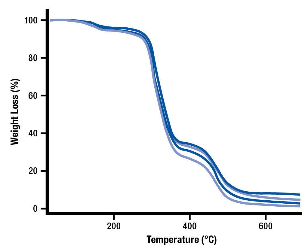
Advantages & Disadvantages
There are several advantages and disadvantages associated with using Thermogravimetric Analysis (TGA) to test the gelation or fusion of PVC and CPVC.
Advantages:
- Many low-cost TGA systems are available
- The tests are relatively easy to perform
- The test is evaluating the polymer itself
Disadvantages:
- High-accuracy TGA systems are expensive
- Low-cost TGA systems have poor ventilation
- Evaluation requires training and experience
- Comparative testing of good and bad product is required to determine pass or fail curves
Differential Scanning Calorimetry (DSC) Test
The Differential Scanning Calorimetry (DSC) system heats the polymer sample at a specified rate while the heat flow from the sample is measured. The result of the test is a curve showing the heat flow of the sample on the vertical Y axis and the temperature of the sample on the horizontal X axis.
Since the test involves heating of PVC or CPVC, proper PPE and ventilation is required to conduct this test.
The purpose in using Differential Scanning Calorimetry (DSC) testing for performance PVC and CPVC is that a 100% gelated or fused polymer matrix will heat up as one component because they are fully combined. In contrast, any un-gelated heat stabilizers and fillers will heat up a different rate than the rest of the polymer components. Since it is rare to achieve 100% gelation, the results will have 2 dips in the curve. The area of these curves represent the amount of material which is gelated in the first portion and the amount of un-gelated or unfused material in the second portion.
The DSC software can determine the amount of PVC or CPVC that is in the gelated and un-gelated portion of the DSC curve.
The general methodology of Differential Scanning Calorimetry testing is common:
- A small test sample is cut from the product
- A sample is sealed into a container and an empty comparison container is also sealed
- The samples are placed into the DSC machine and the machine cycle is started
- The sample is subjected to a heat source which heats the sample as well as the comparison containers
- The heat flow for both containers is constantly measured by a computer which generates a heat flux curve and calculated the percentage of gelation or fusion
Example of DSC Curve for 75% Gelation of Fusion
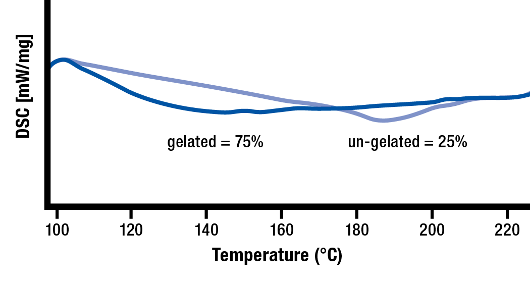
Example of DSC Curve for 95% Gelation of Fusion
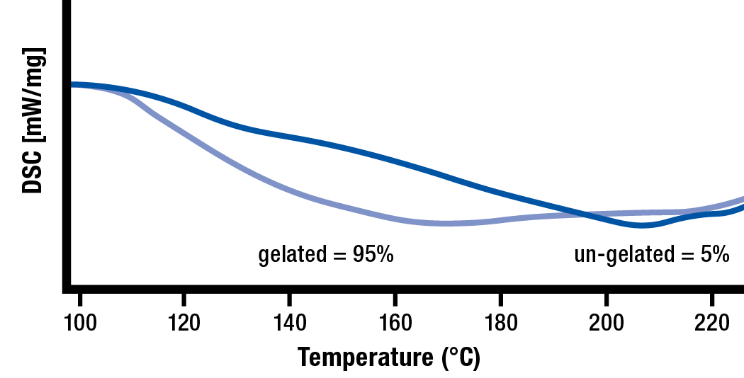
Advantages & Disadvantages
There are several advantages and disadvantages associated with using Differential Scanning Calorimetry (DSC) to evaluate the gelation or fusion of PVC and CPVC.
Advantages:
- The test is evaluating the polymer itself
- Percentage gelation is analyzed and provided by the DSC system
Disadvantages:
- DSC systems are expensive
- Sample preparation requires training and experience
PVC & CPVC Powder, Pellets, and Regrind
Powder
Many processors use PVC or CPVC powder, which is commonly compounded in-house using large blenders. This PVC or CPVC powder is mixed and blended at controlled shear rates and temperatures to help provide a consistent material source with the same amount of time, temperature, and shear history with each batch.
It is best to use the same blending equipment for each lot to prevent variation in the quality of your PVC or CPVC source material. Most material suppliers provide you with information about the blending equipment used and the location of the facility. Many suppliers will be able to provide you with material from the same facility or line if you work with them.
When powder is melted and processed, most of the gelation takes place in the barrel. The processor has significant control over degree of gelation when the PVC or CPVC is in powder form. Keep in mind, powders from different suppliers will have completely different time, temperature, and shear histories — requiring significantly different processes to obtain similar final part performance.
With powder, the processor controls a high percentage of the gelation or fusion during processing.
PVC or CPVC Powder on Gelation or Fusion Arc
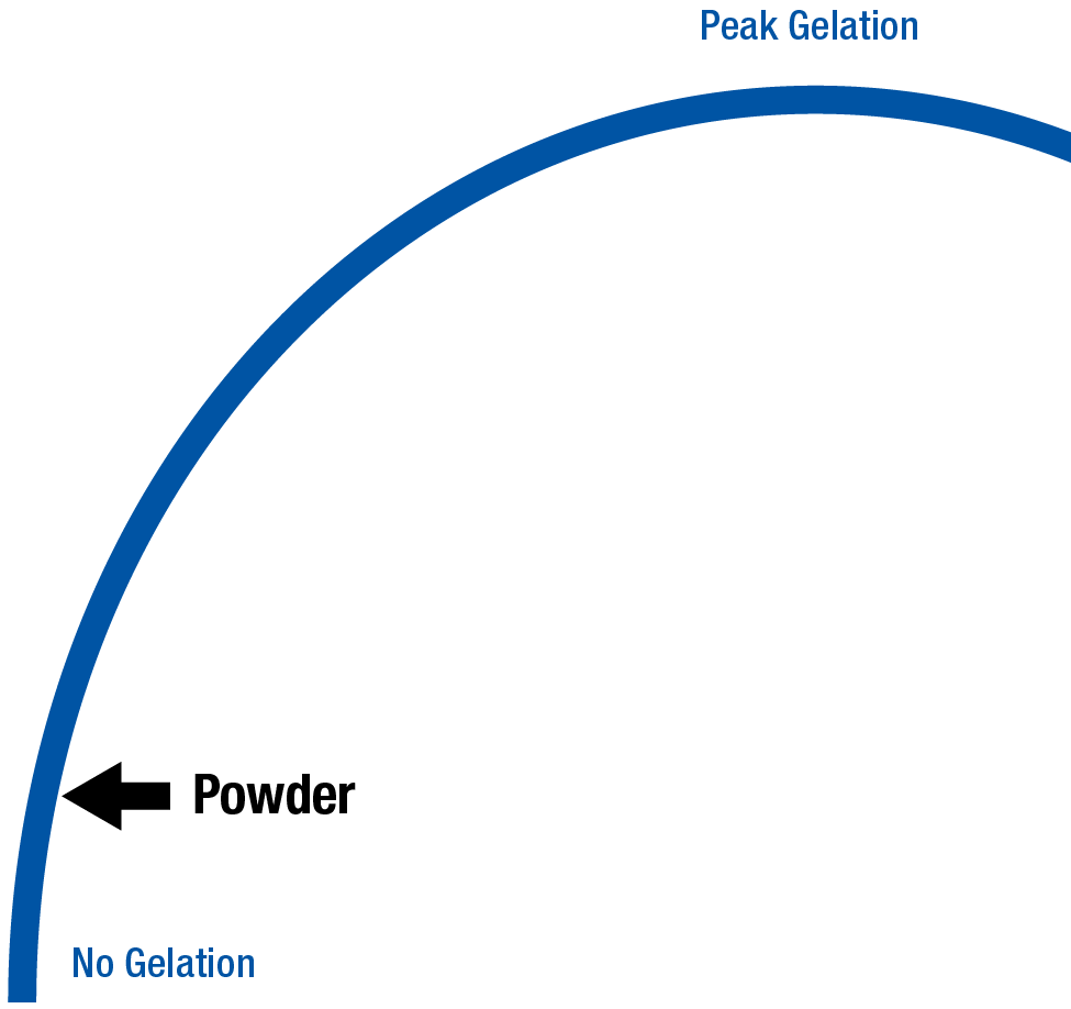
Pellets
When PVC or CPVC powder is processed into pellets, the polymer is exposed to another time, temperature, and shear history. Pelletization takes place with an extruder where the PVC or CPVC powder is melted, extruded, and cut into pellets. As a result, more progression towards gelation or fusion has occurred in the pellets vs. its original powder form.
As with powders, it is important for your pellet supplier to use the same extrusion line to process your PVC or CPVC pellets. A change in equipment or processing conditions will cause a significant change in the amount of gelation or fusion present in the pellets you receive. Essentially, PVC or CPVC lots received from different pelletizing lines will have different time, temperature, and shear histories — requiring different amounts of work during processing to reach peak gelation or fusion.
It is equally important that your pellet supplier get the same quality powder from the same blending equipment each time. A change in the time, temperature, and/or shear history in either the powder blending or pelletization process will have a significant effect on the gelation of the final product.
PVC and CPVC powders are very sensitive to time, temperature and shear when compounding into pellets. During pelletizing the blending and extrusion equipment are critical to these properties and should not be altered from lot to lot, as changes may affect material properties. All changes in time, temperature, or shear during the pelletization process must be communicated by the material supplier since these changes can alter the final process. When pellets incur more processing time/temperature/shear, they are likely to encounter increased degradation when processed.
With pellets, the processor typically controls half of the gelation or fusion process.
PVC or CPVC Pellets on Gelation or Fusion Arc
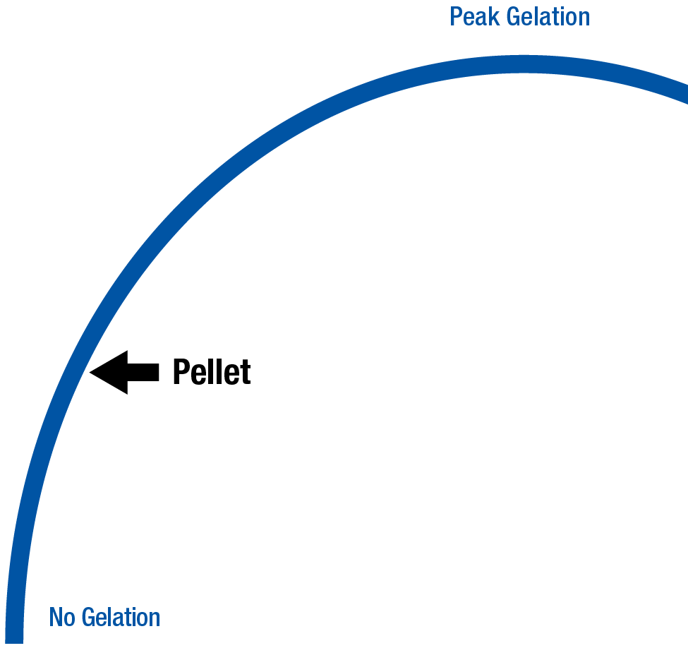
Regrind
There are many concerns when processing reground PVC and CPVC since the regrind material already has multiple histories of time, temperature, and shear. These concerns include:
- Powder Blending and Mixing
- Polymer Pelletizing
- Material Drying
- Melt Processing
- Grinding into Regrind
All of the above processes involve exposing the polymer to heat and shear. Sometimes this exposure takes place for hours as with material drying. Low RPM grinders are strongly recommended when regrinding PVC and CPVC, as they generate less heat during the grinding process.
Since the PVC or CPVC may have reached peak gelation or fusion, the reground PVC or CPVC material is much closer to degradation than it was in powder or pellet form. PVC or CPVC regrind is very difficult to process without causing degradation; therefore, lower percentages of regrind are always preferred. Frequent testing & inspection should also be used whenever processing with PVC/CPVC regrind to help identify any degradation that might be occurring.
Be cautious when mixing PVC Pellets with PVC Regrind since they both have different time, temperature, and shear histories. The resulting product may be inconsistent and should be closely monitored. For these reasons it is very important to closely monitor your incoming stream of PVC and CPVC regrind. Higher percentages or low-quality PVC or CPVC regrind will limit the amount of gelation or fusion possible with the final product.
Burnt or Degraded PVC or CPVC
You should never regrind and reprocess burnt or degraded PVC or CPVC. This material has negative value as it will cause rapid degradation of any PVC or CPVC it contacts. Any burnt or degraded PVC or CPVC material that enters the barrel will begin a chain reaction which can reduce the visual appearance, physical properties, and resistance properties of your final product. This means that a small percentage of degraded PVC or CPVC will prevent the material from reaching peak gelation or fusion render the final product useless. This is why the use of regrind must be strictly controlled and monitored in any performance PVC or CPVC applications where high percentages of gelation or fusion is required.
Too much burnt or degraded PVC or CPVC entering the barrel creates an extremely dangerous situation, which can result in the release of toxic chlorine gas — and an explosion of the barrel, die, or hopper. All of these situations have been known to cause serious injury and death at PVC/CPVC processing facilities.
For this reason, it is recommended to avoid putting any visually burnt or degraded polymer in the regrind stream. Sometimes this involves throwing away the entire piece, but it may involve cutting away the burnt or degraded section and retaining the rest of the piece.
Some companies invest in high-speed particle sorting equipment, such as those used in food applications to separate contaminants. As long as your part is not dark in color, these systems can visually sort out pieces of burnt and degraded regrind from the good regrind. These machines are not perfect, but can be great way to help maintain a better, more reliable quality of regrind material.
These are many ways to mitigate the creation of burnt PVC or CPVC, but there are no truly safe ways to reprocess degraded PVC or CPVC. Essentially, degraded or burnt PVC or CPVC should be considered waste and thrown away accordingly.
Burnt or Degraded PVC or CPVC on Gelation or Fusion Arc
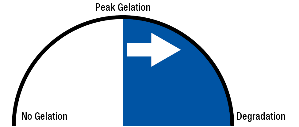
Purging Procedures & Techniques
Definition
By definition, to purge is ‘to get rid of.’ In the case of extrusion, purging ensures that contaminants are removed to prepare for a new, contaminant-free application.
Contaminants include the following:
- Particles, dirt, and dust
- Paper
- Cardboard
- Colorants and additives
- Degraded material and carbon buildup
- Metal flakes from the screw, barrel, and check ring
- Rust from the screw, barrel and die
Plastic Purging Safety
PVC can never be processed in the same extruder that has used Acetal. Likewise, an extruder that was used for Acetal cannot be used for PVC. Any combination of these two materials produces a deadly gas which can also cause an explosion.
There is no material or purging procedure that will allow you to safely process these two incompatible plastics in the same extruder. Properly review all recommended procedures and safety precautions before removing the screw. These operations are highly machine-specific — and injury or death can occur if handled improperly.
Personal Protective Equipment that is required during purging includes:
- Face Shield (or Purge Guard)
- Heat Resistant Gloves
- Long Cotton Sleeves
- Long Pants
- Closed-Toed Shoes
When purging, it is imperative to keep clear of the front zone of the extruder and to never reach around or under the die. Never attempt to clear the die or touch purge with your hands. A brass, plastic, or wood tool should always be used to handle purge. Purge can reach 400 °C (750 °F) and can remain dangerously hot for a long period of time.
Here are some additional guidelines to ensure the safety of yourself and your co-workers:
- Be responsible and aware of your surroundings
- Inform others around you of your tasks
- Never rush
- Follow procedures
- Avoid distractions
- Use the appropriate tools
- Ask for assistance if needed
- Always follow Lock-Out/Tag-Out protocol
Purging Procedures
Phase 1: Preparation
In the initial preparation phase, it is critical that you prepare accordingly and have all your materials present before any purging takes place. Make sure there is at least enough material for purging available to purge twice in case the initial purge is inadequate. There should also be enough of the production material to begin production once the purging is complete.
Phase 2: Initial Purge
The Initial Purge begins with a thorough cleaning of the equipment to remove all traces of the previously used plastics. After the initial cleaning is completed, the Initial Purge Settings are entered into the machine. Once cleaning is complete and the purge settings have been entered, add the required amount of purge material into the hopper and open the feedthroat.
Once the correct purging temperatures are stable, begin purging at low screw rpm . This should continue until the hopper and feedthroat are empty and you can see the screw flights using a mirror.
Phase 3: Final Purge
The third phase of the purging process is the Final Purge. This begins with a final and thorough cleaning of the hopper, feedthroat, and extruder. If purging does not remove all contaminants, you should repeat the initial purging process a second time.
If a second purging does not work, then you may need to try one of the following approaches:
- Use a different purging material or purging procedure
- Remove and clean the breaker plate, filters, and die
- Remove the screw and thoroughly inspect and clean the screw and barrel (last resort)
Phase 4: Production
After purging is complete, production can begin. It can take anywhere from several minutes to several hours for the extrusion process to stabilize.
Purging Techniques
Single Speed Purging
During the extrusion process, a melt bed is established where the material is consistently being melted and conveyed at a consistent screw speed. This melt bed must be broken up during purging to effectively clear out the unwanted material in the screw and barrel.
Single speed purging involves clearing the barrel using one screw speed until it is fully purged. However, using a single screw speed often allows the melt bed to remain in place longer, making the process more difficult. This approach requires significantly more time and consumes more plastic or purging compound to thoroughly clear the screw and barrel.
Variable Speed Purging
During the extrusion process a melt bed is established where the material is consistently being melted and conveyed at a consistent screw speed. If the screw speed is varied during purging, it will help the purging compound break up the melt bed.
Variable speed purging involves the use of abrupt changes in screw speed to help disrupt the melt bed and improve screw and barrel purging. Always keep an eye on the Amperage drawn and do not exceed acceptable limits during purging.
Dry Purging
Dry purging involves pushing as much material out of the barrel as possible before adding the next material to be used. The screw should never be left dry because remaining polymers and additives will bake and stick to the screw as air is introduced to the barrel. This baked polymer will cause degradation, oxidation, and contamination. Dry-purging should only be used to empty the barrel of polymer prior to screw removal.
Wet Purging
You should always use wet-purging so that the screw flights remain full of material at all times. When purging, you should add the next material when the screw flights are visible. Always use a telescoping mirror to look into the feedthroat to verify the screw flights are clear of plastic. The wet-purging method maintains ‘positive flow’, which helps prevent old plastic from baking and sticking to the screw and barrel.
Melt Processing of Polymers
The purpose of melt processing is to first melt the source polymer from a pellet, powder, flake, or regrind state. This polymer melt is combined and mixed with any needed additives, reinforcements, fillers, or colorants, inside the barrel. Lastly, the melted polymer is converted to a useful or sellable product such as a sheet, film, profile, tube, or plastic pellets.
Melting Polymers
When processing polymers, energy is added to the polymer in the form of heat and shear. Heat is typically provided by heater bands around the barrel. Shear is applied through the use of a screw inside of the barrel which rotates in a process which both works and heats the polymer. The material enters the barrel at the Feedthroat where the screw flights are the deepest as a powder, pellets, and/or regrind.
Screw & Barrel Assembly
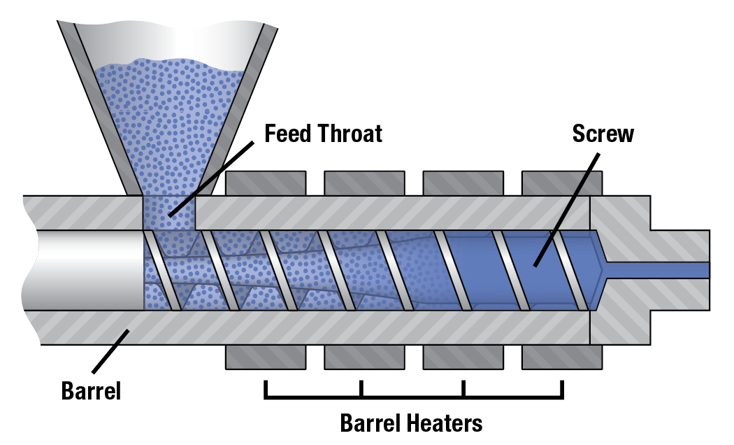
If too much heat or shear is used during processing, the polymer can begin to degrade. To help accurately control the temperature of the polymer, most barrels for extrusion are equipped with cooling fans around the heater bands to prevent the polymer from getting too hot.
The Feed Zone of the screw has the deepest flights for the best material conveyance. For amorphous polymers like PS, ABS, PVC, and PC the rear zone tends to be set to a low temperature for optimum conveyance in the feed zone. For semi-crystalline polymers like PP, PE, PET, and Nylon the rear zone tends to be set to a higher temperature for optimum conveyance in the feed zone.
The optimum rear zone temperature can be determined using a rear zone temperature study. In such a test, different rear zone temperature can be set and the output measured. The rear zone temperature which provides the highest output is likely the best for that polymer in that machine.
As the polymer is conveyed forward, the flights begin to reduce in depth which compresses the polymer. This polymer compression occurs in the Transition Zone, also known as the Compression Zone.
The compression of the polymer in the Transition Zone puts work and energy into the polymer through a process called Shear. The combination of shear and barrel heat causes the polymer to soften and melt within the barrel. To help prevent excessive shear and heat generation, a screw designed for your material is preferred.
A screw intended for amorphous polymers tends to have a large compression zone in the center. This long compression zone helps to gradually heat and shear the amorphous polymer. Amorphous screws often have compression zones which consume between 60 and 100% of the overall screw length.
A screw intended for semi-crystalline polymers tends to have a large feed zone in the back of the screw. This long feed zone helps provide time to heat and soften the semi-crystalline regions before they are sheared in the compression zone. Many semi-crystalline screws have feed zones consuming between 40 and 60% of the overall screw length.
The Metering Zone at the end of the screw has the shallowest flight depth. This helps pump the melted polymer to the front of the screw. The metering zone can also help mix the polymer especially when mixing elements are incorporated. More about basic screw design is covered in the portion of the book covering single-screw and twin-screw extruder designs.
Screw Zones
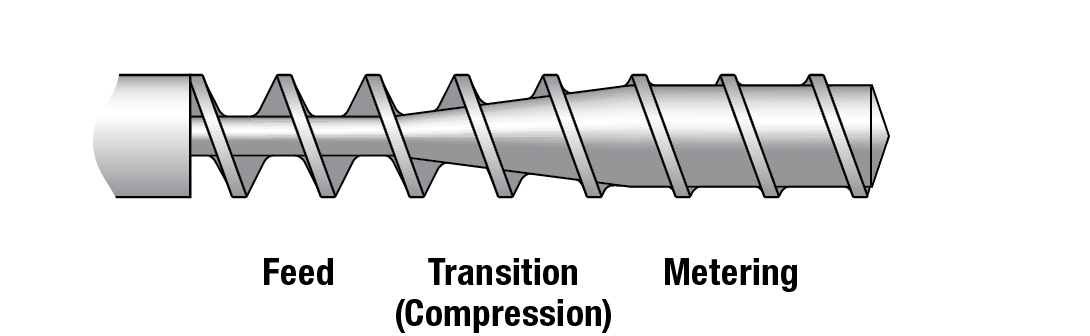
When melted properly, the polymer at the front of the screw is ready to be processed. During processing, the polymer is forced to flow using pressures up to 1,500 psi (pounds per square inch) or 100 bar for extrusion and blow molding processes or 15,000 psi (pounds per square inch) or 1000 bar for injection molding processes.
Once processed into its final form, the polymer is cooled down enough to maintain its final form and function. During the cooling process, energy is removed from the melted polymer, causing the final product to shrink. In the case of injection molding, the final part will have smaller dimensions than the injection mold. In the case of extrusion, the final product will shrink in the downstream cooling system. The slower the polymer cools, the more shrinkage the polymer encounters.
Some polymers such as PVC are often processed in a vented barrel to release moisture and volatiles from the melted material. The screw used for such extruders have a vent zone which has deep flights similar in depth to the feed zone. The depth of this zone creates a low-pressure zone where the polymer stays in the barrel where volatiles can be vented through a hole in the barrel.
If material moisture is being vented, the barrel will usually vent to atmosphere, but more volatile materials like PVC will often use a filtered vacuum system to actively remove the volatiles from the barrel.
Vented Screw Zones
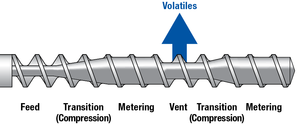
Viscosity, Shear Rate, and Orientation
Viscosity is a measure of a polymer’s resistance to flow. Shear rate is a function of the material flow rate and the cross-sectional area of flow. Shear rate is increased by either reducing the cross-sectional area or increasing the material flow rate. With polymers, an increase in shear rate causes the polymer chains to align in the direction of flow. This alignment is called orientation.
The polymer is stronger in the direction of flow due to polymer chain orientation. Slowing the product cooling with increased material or coolant temperature reduce this orientation. In some processes such as blown film and pipe extrusion, the polymer is stretched in the direction perpendicular to flow, resulting in what is called bi-axial orientation. This dual orientation causes the polymer to be strong in multiple directions.
Polymer Cooling Rate
When cooled, polymers will shrink as the molecules reduce their energy level and consume less space, but the amount of shrinkage that occurs depends on the cooling rate. With all polymers, a slower cooling rate allows for more time for polymer chain mobility. This increased chain mobility allows the polymer chains to pull themselves closer together due to a large amount of intermolecular attraction.
The cooling rate is an important factor in plastic part dimensions. The slower the cooling rate, the more the polymers will have time to shrink due to intermolecular attraction. The graph below provides a basic example of how the polymer dimensions will increase with a faster cooling rate.
Cooling Rate and Part Dimensions
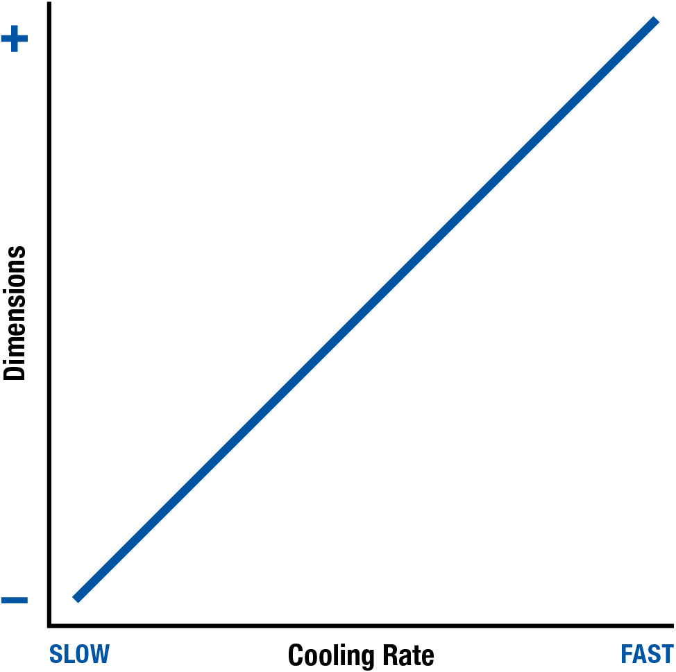
The hot plastic is typically cooled using water as a coolant. For injection molding and blow molding processes, this cooling takes place inside a water-cooled mold. For extrusion processes, this cooling typically takes place inside a water tank or water chilled rollers. Blown Film is one process that uses forced air as the primary method of polymer cooling. The two factors that affect Cooling Rate are temperature and cooling time.
Temperature
The higher the temperature of the melted plastic or coolant, the slower the cooling rate. The rate is slower because it takes longer for the heat to be removed from the polymer resulting in smaller dimensions. Likewise, lower temperatures cause the heat to be removed faster, resulting in a faster cooling rate. In general, lower temperatures cause larger dimensions and higher temperatures cause smaller dimensions.
Temperature and Part Dimensions
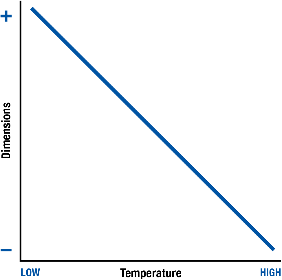
Cooling Time
The time the plastic is being cooled is the cooling time. The cooling time refers to the time when the heat is being removed from the plastic quickly. The longer the Cooling Time, the quicker the heat is being removed from the polymer. For injection molding and blow molding processes, this is the time the mold remains closed after the plastic has been forced against the mold surface. For extrusion processes, cooling time refers to the time the plastic remains in the cooling system, such as the cooling tank or chiller rollers. In extrusion, a faster line speed causes a lower cooling time.
A longer cooling time causes a faster cooling rate which results in larger dimensions. Shorter Cooling Times remove less heat resulting in a slower cooling rate and smaller dimensions. For these reasons, a longer cooling time causes larger part dimensions while a shorter cooling time will result in smaller dimensions.
Cooling Time and Part Dimensions
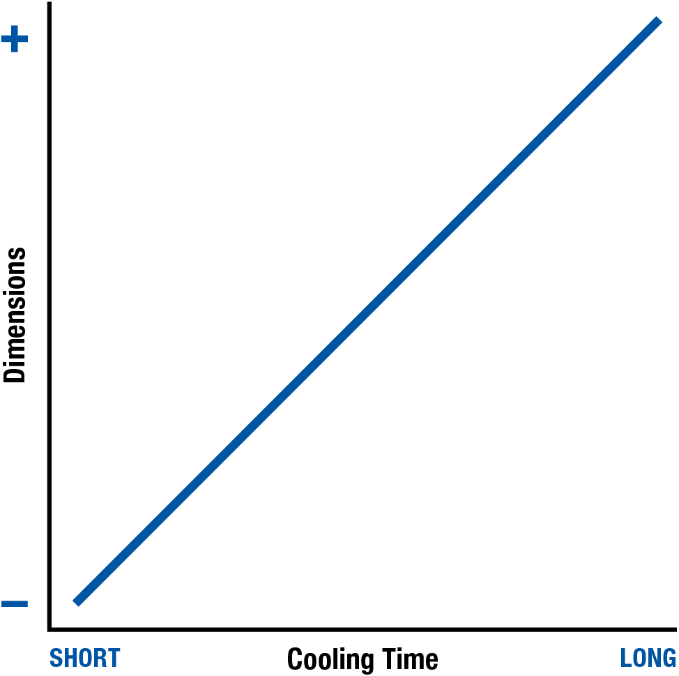
Basic PVC & CPVC Machinery Concerns
The chlorine present in PVC and CPVC will promote corrosion of any surface it touches. The chlorine gas which is given off when processing chlorine will promote oxidation with any metal surface it contacts.
All metal surfaces should be made of stainless steel whenever possible because of its inherent resistance to corrosion and . Corrosion-resistant coating such as chrome, teflon, rubber, plastic, or a powder-coat (similar to paint, but much more durable) tend to work very well, except they can often be removed when abraded or impacted. In many cases, processors use stainless steel with a corrosion or oxidation resistant coating to maximize the corrosion and oxidation resistance of their metals.
For process machinery, stainless steel is the preferred material for exposed surfaces such as the screw and barrel. For example, a PVC screw may be constructed from chrome and teflon-coated stainless steel with a highly-polished ‘Class A’ finish.
All surfaces where the polymer flows must be streamlined with no places where the polymer can stagnate and begin degrading. The barrel and screw surfaces should be polished to a smooth, mirror-like finish. For injection molding, the inside of the end cap and nozzle must also be polished, ensuring they are perfectly centered and aligned so the internal surfaces are smooth to the nozzle tip. For extruders and blow molders, the inside of the adaptor and die should also be polished, with all components perfectly centered and aligned to ensure smooth internal surfaces to the exit of the die.
Injection molders and blow molders will also use stainless steel molds and tie bars. Extruders will use stainless steel dies, cooling tanks, and downstream equipment. Plastic pipes and hoses with brass fittings are also common to prevent oxidation of the water system.
All exposed surfaces — including the outside of the mold or die — should be cleaned regularly with an acid neutralizer to mitigate the impact of chlorine gas and then sprayed with a surface protectant or lubricated if it is a moving part.
Scientific Documentation for Extrusion
Documentation Concerns
The more material and process information you can document for each production run, the better you can identify changes when they occur. With the right information, you should be able to replicate the product from previous runs using similar process settings.. When the proper documentation is being used, it will help technicians conduct startup and troubleshooting events with much-higher confidence.
In this portion of the guide, we will review the 3 primary forms of documentation — as well as process calculators used for documentation:
- Setup Sheet
Document process inputs - Process Sheet
Document process outputs - Process Change Log
Document all process changes
For Performance PVC and CPVC product, it should also include run-specific documentation.
Process Inputs vs. Process Outputs
Process inputs are the machine-dependent parameters entered into the processing equipment. These settings include: screw speeds, barrel temperatures, and puller speed.
Process outputs are machine-independent, process-specific parameters, which result from the process. These outputs include: temperatures, line speed, pressures, weights, amps, as well as any additional information important to the product or process. Additional information which are also considered process outputs include: part measurements, material dewpoint, quality information, clamp tonnage, photographs, and observations.
Open Loop vs. Closed Loop Process Controls
Open loop process control systems guide the process through a series of predetermined steps. After the process is complete, the cycle starts over again. As the process is in operation, the operator is left to examine the process outputs for inconsistencies. The operator is then responsible for correcting the process for inconsistencies. The more inconsistent a process is, the harder it becomes for the operator to correct. The accuracy of an open loop process is solely dependent on the knowledge and experience of the operator.
Closed loop process control systems are designed to automatically correct variations in the process. Electrical measuring devices, such as a pressure gauge, are used to measure the process outputs. A feedback loop is used to transfer process outputs to the closed loop process control system. A microprocessor is then used to evaluate the process outputs for variations. The microprocessor compares the actual process outputs to the desired process outputs. If a variation is detected, the microprocessor determines how much of a particular action is required to correct the process. The signal is then sent back to the equipment, and the process is adjusted. The quick response of closed loop process control systems make them effective in controlling and reducing variations within a process.
Machine Documentation: Setup Sheet
Each extruder will have its own documented set of process inputs, which is typically referred to as a Setup Sheet. Setup sheets are a record of the process inputs or settings which made good product. This machine specific documentation is very helpful to technicians when installing and setting up the machinery.
The setup sheet should include critical information pertaining to the specific run and should be obtained each time the process achieves first-piece-approval. This sheet should contain general information as well as machinery settings.
The following subchapters detail common information that can be recorded on each section of the Setup Sheet.
Setup Sheet: General Information
- Date and Time
- Material Type, Grade, and Lot #
- Percentage Regrind and Additives Used
- Additive and/or Colorant Grade and Lot #
- Processing Machinery ID and/or Line #
- Product Name or ID
- Processing Equipment ID
- Adaptor
- Gear Pump
- Die
- Calibrator/Sizing
- Screen Pack Composition
- Auxiliary Equipment IDs
- Material Dryer
- Hopper and Hopper Loader
- Water Temperature Controller(s)
- Conveyor, Separator, and/or Grinder
- Auxiliary Sensors, or Process Control
- Any Secondary Operation Equipment
- Downstream Processing Equipment
- Downstream Inspection Instruments
- Specialty Tools or Gauges Used for Production
- Any important notes on the condition of the…
- Material
- Die
- Machinery
- Auxiliary Equipment
- Anything else necessary to make good product
Setup Sheet: Machinery Inputs
- Extruder and Die Setpoints
- Screw
- Screw RPM (closed loop)
- Screw Percentage Power (open loop)
- Screw AMP (closed loop)
- Die or Head Pressure (closed loop)
- Barrel, Adaptor and Die
- Feed Block Temperature (closed loop)
- Feed Block Coolant Flow (open loop)
- Zone Temperature (closed loop)
- Zone Percentage Power (open loop)
- Gear Pump
- Gear Percentage Power (open loop)
- Gear RPM (closed loop)
- Gear AMP (closed loop)
- Die Pressure (closed loop)
- Pressure Change (closed loop)
- Automatic Screen Changer
- Pressure Setpoint (closed loop)
- Timer Setpoint (closed loop)
- Speed Setpoint (closed loop)
- Barrel Vent Vacuum
- Vacuum Setpoint (closed loop)
- Vacuum Percentage (open loop)
- Air Pressure (pipe, tubing, blown film, and profile)
- Pressure Setpoint (closed loop)
- Percentage (open loop)
- Screw
- Material Setpoints
- Material Dryer Temperature
- Material Blending (for each component)
- Percentage (open loop)
- RPM (closed loop)
- Material Feed Rate (closed loop)
- Material Feeder or Crammer
- RPM (closed loop)
- Percentage (open Loop)
- Mass Flow Rate (closed loop)
- Ratio with Screw RPM (Closed Loop)
- Downstream
- Calibrator and/or Cooling Tank
- Vacuum Setpoint (closed loop)
- Vacuum Percentage (open loop)
- Coolant Temperature (closed loop controls)
- Coolant Pressure (closed loop controls)
- Coolant Flow (open loop controls)
- Spray Tank
- Spray Water Temperature (closed loop controls)
- Spray Water Pressure (closed loop controls)
- Spray Water Flow (open loop controls)
- Cooling Rolls
- Water Temperature (closed loop controls)
- Water Pressure (closed loop controls)
- Water Flow (open loop controls)
- Roll RPM (closed Loop)
- Roll Pressure (closed Loop)
- Roll Percentage (open loop)
- Puller or Wind-Up
- Pressure (closed loop controls)
- Speed (closed loop controls)
- Percentage (open loop controls)
- Ratio with Screw RPM (closed loop controls)
- Ratio with Material Feed (closed loop controls)
- Cutter or Saw
- Interval Timer (closed loop controls)
- Distance (closed loop controls)
- Cut Timer (closed loop controls)
- Clamp Pressure (closed loop controls)
- Clamp Percentage (open loop controls)
- All setpoints for Auxiliary Equipment, such as:
- Labelers
- Printers
- Trimmers
- Roll Stacks
- Dump Tables
- Forming and Shaping Equipment
- SPC Equipment
- Calibrator and/or Cooling Tank
Machine Documentation: Process Sheet
Each product line should have its own set of process outputs, typically referred to as a Process Sheet. Process sheets are a record of the actual process that made good product. This process specific documentation is very helpful to technicians when starting up and troubleshooting the process. There should be an approved standard process sheet used as a reference during each production run , as well as run-specific process sheets filled out during each first-piece approval.
Process Sheet: Process Outputs
Below are examples of common process outputs and information which can be obtained:
- Extruder and Die Setpoints
- Screw
- Screw RPM
- Screw AMP
- Barrel, Adaptor and Die
- Feed Block Temperature
- Feed Block Coolant Flow
- Zone Temperatures
- Material Temperature
- Head Pressure
- Die Pressure
- Barrel Residence Time (see calculator)
- Gear Pump
- Gear RPM
- Gear AMP
- Pressure Change
- Barrel Vent Vacuum
- Picture of Vent
- Vacuum Pressure
- Air Pressure (pipe, tubing, blown film, and profile)
- Air Pressure
- Air Flow
- Air Temperature
- Screw
- Material
- Material Dryer Temperature
- Dryer Dewpoint
- Dryer Residence Time (see calculator)
- Material Feed Rate
- Material Feed RPM
- Downstream
- Ambient Conditions
- Temperature
- Humidity
- Die Exit
- Picture (top and side)
- Exit Temperature (IR or surface probe)
- Calibrator Tank
- Distance between Die and Calibrator
- Vacuum Pressure
- Coolant Temperature
- Coolant Pressure
- Coolant Flow
- Coolant Water Level
- Coolant Tank
- Distance between Calibrator and Coolant Tank
- Coolant Temperature
- Coolant Pressure
- Coolant Flow
- Coolant Water Level
- Spray Tank
- Picture of Spray Configuration
- Spray Water Temperature
- Spray Water Pressure
- Spray Water Flow
- Cooling Rolls
- Water Temperature (closed loop controls)
- Water Pressure (closed loop controls)
- Water Flow (open loop controls)
- Roll RPM (closed Loop)
- Roll Pressure (closed Loop)
- Roll Percentage (open loop)
- Tank or Rolls Exit
- Picture (top and side)
- Exit Temperature (IR or surface probe)
- Puller or Wind-Up
- Pressure
- Speed
- Cutter or Saw
- Length
- Picture of Cut (top and side)
- Clamp Pressure
- Ambient Conditions
- All relevant outputs for Auxiliary Equipment, such as:
- Pressure
- Speed
- Temperature
- Flow
- Measurement
- Take reference photographs whenever possible, such as:
- Labels
- Printing
- Stamping
- Trimmings
- Punches
- Textures
- Acceptable Defects
- Unacceptable Defects
- Product Quality and Output Measurements, such as:
- Dimensions
- Weight per Length
- Output Rate
- Quality Notes (with pictures)
Machine Documentation: Process Change Log
A process change log should be maintained throughout each production run, recording every change made from first-piece approval to the last piece produced. Keep in mind that any seemingly minor change could provide critical information for another technician.
An accurate history of each production run includes the setup sheet, process sheet, and process change log. This is extremely helpful when starting up, troubleshooting, and isolating good and bad product when a quality issue is detected.
Process Change Log: Document All Changes
- Change Made
- Day and Time of Change
- Product, Case, or Roll Number
- Old Setting or Condition (see below)
- New Setting or Condition (see below)
- Reason for Change
- Result of Change
- Process Parameters Verified
- Name or Initials of the Technician
- Name or Initials of Quality Inspector
- Process Change:
- Initial Process Setpoint
- Final Process Setpoint
- Material Change examples:
- New Material Lot
- Old Lot #
- New Lot #
- Regrind % Change
- Old Percentage
- New Percentage
- Colorant
- Old Colorant and Lot #
- New Colorant and Lot #
- New Material Lot
- Equipment Change/Replacement
- Old Equipment ID
- New Equipment ID
- Die, Machinery, Downstream, or Equipment Repair
- Repair Being Performed
- Person Conducting Repair
Run-Specific Documentation for Performance PVC & CPVC
Performance PVC and performance CPVC refer to polymers which must meet stringent strength or resistance properties. For the purpose of this guide, we will occasionally differentiate these polymers from non-performance PVC/CPVC polymers in cases where the application has specific appearance or dimensional requirements but lacks stringent performance requirements.
When a significant change in time, temperature, or shear occurs, a reciprocal change will likely be needed in the process. For example, if the new material or machinery causes an increase in time, temperature, or shear history of the polymer, you may have to take some time, temperature, or shear away by lowering screw speed or lower melt temperature.
The points abouve are discussed in detail in the chapter on Time/Temperature/Shear Relationship for PVC and CPVC.
Run-specific documentation represents variables which are specific to the time, temperature, and shear effects on gelation or fusion of performance PVC or CPVC. Because changes in processing equipment have a large impact on this time, temperature, and shear relationship, it is always preferred to process PVC and CPVC on the same or similar machinery whenever possible. For example, if you make good product on an extruder with screw cooling and barrel cooling fans, it would not be recommended to run the same product on machinery without these capabilities since the performance PVC or CPVC will likely degrade without significant changes to the process.
With time, temperature, and shear documentation, there are both primary and secondary considerations when processing performance PVC/CPVC:
- Primary Considerations
These have the greatest impact on gelation or fusion as well as on polymer degradation - Secondary Considerations
These have a lesser impact on gelation or fusion as well as on polymer degradation.
Time, Temperature & Shear Considerations
- Primary Time Considerations
- Barrel Residence Time
- Regrind Percentage
(regrind has a higher time/temperature/shear history)
- Secondary Time Considerations
- Dryer Residence Time
- Primary Temperature Considerations:
- Material Temperature
- Barrel Cooling Fans: YES/NO
(barrel cooling fans reduce temperature and degradation) - Barrel Zone Temperatures
- Setpoint
- Actual
- Screw Cooling: YES/NO
(screw cooling reduces temperature and degradation)
Screw Coolant Temperature- To Process
- From Process
- Secondary Temperature Considerations
- Dryer Temperature
- Downstream Coolant Temperatures
- Exit Temperatures (IR or surface probe)
- Primary Shear Considerations
- Head Pressure
- Screw AMPS
- Output Rate
- PVC-Specific Screw: YES/NO
(such screws reduce shear and degradation)
- Gelation or Fusion Test Results
- Testing Method Used
- Testing Results: PASS/FAIL
- Measurement from Testing Equipment
- Testing Method Used
Barrel Residence Time Calculation
Before you can calculate the barrel residence time, you will first need to know the amount of material the screw holds. This should be provided to you by your screw manufacturer in kg or lbs of Polystyrene, which has a specific gravity of 1. You will need to convert that volumetric capacity to your material by multiplying that capacity by the specific gravity of your material.
Calculation Notes:
- Screw Capacity = Amount of material the screw can contain in polystyrene
- Specific Gravity = Specific gravity of your material
- (Screw Capacity ÷ Output Rate) = Weight per Hour
- (Weight per Hour × 60 minutes per hour) = Estimated Barrel Residence Time
Estimated Barrel Residence Time Calculator
Dryer Residence Time Calculation
To determine the Dryer Residence Time, you must first determine the Dryer Capacity. Keep in mind, dryers are rated for polystyrene which has a specific gravity of 1.0. Therefore, you will have to adjust the capacity for the specific gravity of your material.
Calculation Notes:
- Dryer Capacity = Amount of material the dryer can contain in polystyrene
- Specific Gravity = Specific gravity of your material
- (Dryer Capacity ÷ Output Rate) = Estimated Dryer Residence Time
Estimated Dryer Residence Time Calculator
General Rules for Processing
When setting up or maintaining a process, there are five general rules to follow to ensure optimum results.
Rule 1: Make one process change at a time
Once the initial process parameters are entered, adjust only one aspect of the process at a time. When a change is made, it’s imperative to wait for the results to take place before making another adjustment. This rule ensures you know the specific cause and effect of any change made to the process.
Rule 2: Make significant changes
Make sure any change to the process is large enough to make an observable effect. If an adjustment is too small, it may not affect the process enough to make a logical judgment. For example, a 3° drop in coolant temperature may not produce a visible change, but a 10° or 20° change could completely resolve the issue.
Rule 3: If a change does not help, change it back
Once you’ve determined a change was ineffective, return that process parameter back to where it was. Otherwise, you may cause new defects later on. Remember that each change to the process will slowly shift the parameters away from the initial process.
Rule 4: Document the process
Once a process is established and approved, document the process. Many companies have an initial setup sheet used to get the machine started, but do not document the processing conditions at the time of first piece approval. If the approved process is not documented, the technicians may not have enough information to make accurate decisions. Be sure to document both the process inputs that are entered into the machine AND the outputs that result from the process.
Rule 5: Document all changes to the process
Once the initial process is documented, all parameter changes and their associated results must also be accurately documented. The purpose of documentation is to have an accurate record of the changes made to the process and the results of the changes. Good documentation is critical to scientific troubleshooting. In order to make logical decisions, a processor must have access to relevant information.
Quality Assurance & Quality Control
The industry trend is to move towards quality assurance (QA). However, the difference between quality control (QC) and quality assurance (QA) with respect to plastics processing, is not always clearly understood. In general, quality assurance involves producing the acceptable product using the same process each and every production run.
Although there is much more behind both quality control and quality assurance practices, this section will cover some basic concepts critical to plastics product quality. The following sections of the guide cover factors important to plastic product quality.
Subjective Quality Standards
According to the Oxford Dictionary, ‘Subjective’ is defined as ”based on or influenced by personal feelings, tastes, or opinions”. Subjective quality involves accepting or rejecting product quality based on the opinion of the person inspecting the product.
Subjective standards are those which might vary from person to person, depending on the experience and knowledge of the person inspecting the product. This typically involves determining whether the product is acceptable or rejected based on the product inspector’s opinion. Examples of subjective quality criteria include visual defects such as sinks, warpage, surface finish, shiny spots, dull areas, and scratches. With good training, experience, and knowledge of the customer’s requirements, a quality inspector can make educated decisions and determinations based on whether the product is good or bad. However, these decisions can still vary from one inspector to another.
When quality standards are subjective, it may require the processor to meet slightly different product quality requirements every time the product is run. This means the process which ran acceptable product during one production run may not be acceptable during another production run. This happens even if the product from the 2 different runs is identical. In such cases, it is not possible for a plastics processor to ensure quality assurance for the customer, as a different process may be required to meet changing quality criteria with each production run.
Although there will always be the need for quality personnel to make subjective judgment calls in questionable situations, the best practice is to evaluate product to a consistent and objective quality standard each and every production run.
Objective Quality Standards
According to the Oxford Dictionary, ‘Objective’ is defined as “not influenced by personal feelings or opinions in considering and representing facts.” Objective Quality Standards involve accepting or rejecting product quality based on specific quantitative or comparative standards.
Quantitative standards are those which can be measured, such as a specific dimension, product weight, or impact strength. These standards also include quality aspects which can be measured with gauges such as a go/no-go gauge, fit gauge, colorimeter, or gloss meter. Quantitative standards can be made by different people with the expectation that they will come to the same conclusion. For example, if the acceptable dimension is 3.000mm +/- 0.020mm, then anyone encountering a measurement of 3.005mm would agree the dimension is within specification. Advanced quality standards such as Geometric Dimensioning and Tolerancing (GD&T) provide methods for quantifying complex measurements such as surface, flatness, concentricity, and maximum or minimum material conditions. GD&T measurements are typically measured using advanced equipment such as a Coordinate Measuring Machine (CMM), which can take many measurements while using a computer to quantify the measurement objectively.
In plastics processing, many quality requirements — such as acceptable levels of weld lines, discoloration, sinks, or shine — can be challenging to quantify objectively. Over time, quality makes judgement calls on what is acceptable or unacceptable as well as what is questionable – these can become quantitative standards when quality accurately documents what should and should not be accepted using photos, diagrams, or measurements. For example, the extent of a sink or discoloration could be measured and quantified. High quality images and retained quality samples are extremely helpful in ensuring different quality personnel determine product quality using the same objective quality standards.
Objective quality standards apply not only to the product being inspected, but also to the process used to manufacture it.. For example, the process itself can have maximum and minimum limits on die pressure, material temperature, barrel pressure, weight/length, tank coolant temperature, dimensions, and line speed. Some of these limits can be monitored directly by the machine controls, others must be measured with a temperature probe or weighing scale. Plastics processors who provide true quality assurance to their customers have systems in place to ensure that both the product and the process remain consistent from run to run.
Objective quality standards help ensure the technician can produce product the customer will find acceptable — each and every production run.
Quality Control
For plastics processing, quality control involves inspecting product during first piece approval and during production to prevent defects from getting to the customers. There are many quality strategies focusing on how much product is inspected at specific intervals, most of which are designed to balance the risk of bad product getting to the customer with the cost associated with product inspection. In general, the goal of quality control is to create inspection systems to prevent bad or faulty product from reaching the customer. Statistics and proper inspection strategy can significantly improve the effectiveness of your quality control systems. Aside from routine inspection, quality control does not take any steps in preventing bad product except through first piece approval at the start of a production run.
Quality control is always a key aspect to customer retention since it can be devastating when the customer receives bad product, but it is not a substitute for effective quality assurance techniques. In general terms, quality control is focused on preventing bad product from reaching your customer, but not ensuring that there is consistency when a product is manufactured by the production machinery.
Quality Assurance
For plastic processing, quality assurance starts with making acceptable product that conforms to objective quality standards with process which conforms to the approved documented process. In practice, this involves verifying both the product meets objective quality standards and the process conforms with the approved process sheet. This dual product and process approval should take place at first piece approval, at pre-determined time intervals, and after any significant change is made to the process. Significant changes include a material lot change, adjustment to regrind percentage, color change, machinery repair, or equipment change.
If acceptable products are being produced with an approved process during every production run, then quality has a high level of confidence that the customer is receiving quality products over time. This is the foundation of Quality Assurance for plastics processors. With most plastics, following the entire process sheet for every production run helps maintain strong process consistency.
Quality Assurance for PVC & CPVC
With respect to PVC and CPVC, the process-specific documentation portion of the process sheet should be duplicated each and every time. On every production run, the product should have the same line speed, weight/length, tank coolant temperature, etc., as these parameters do not have a significant effect on gelation or fusion of performance PVC/CPVC. In this case, quality assurance involves making sure these remain the same every time the process runs, regardless of the shift personnel.
With PVC and CPVC, the run-specific documentation portion of the process sheet should be duplicated whenever the source materials is similar. When the source material is different, these may be adjusted to achieve the proper time, temperature, & shear balance complication to reach the amount of gelation or fusion required to meet end-use requirements. For performance PVC/CPVC, you may need to reduce the material temperature or screw speed to compensate for a material lot that degrades easily or was dried twice. Adversely, you may have a part which is visually acceptable, but is failing performance testing. A screw speed increase could be helpful to increase the amount of gelation or fusion in your final performance PVC/CPVC product. The more documented history you have from your material suppliers, the more likely you will be able to compensate for these changes. When possible, work with your PVC/CPVC supplier to obtain more consistent source material over time.
Scientific Troubleshooting
Scientific processing involves developing an acceptable process and, once approved, thoroughly documenting this process. This approved process documentation must be used during startup and troubleshooting to best match-up the process with the standard.
Process Development
The purpose of melt processing is to first melt the source polymer from a pellet, powder, flake, or regrind state. This polymer melt is combined and mixed with any required additives, reinforcements, fillers, or colorants inside the barrel. Lastly, the melted polymer is converted to a useful or sellable product, such as a sheet, film, profile, tube, or plastic pellets. Much of this is covered in the Melt Processing of Polymers section of this guide.
Once a process which produces an acceptable product is established, it must be properly documented.
Process Documentation
The more material and process information you can document for each production run, the better you can identify these changes when they occur. With the right information, you should be able to repeat the product from previous runs with similar process settings. Much of this is covered in the Scientific Documentation section of this guide.
Proper documentation will help technicians conduct startup and troubleshooting events with a much higher level of confidence.
Your standard process documentation should include the following:
- Setup Sheet
Document process inputs - Process Sheet
Document process outputs - Process Change Log
Document all process changes
For Performance PVC and CPVC products, it should also include run-specific documentation.
Initial Troubleshooting
When a defect is found, thoroughly review the product for all defects present at that time and fix any obvious issues such as undried material, dirty die, clogged vent, or equipment damage. This portion of scientific troubleshooting is where the experienced technician has the greatest advantage due to their history working with these products, dies, material, and/or machinery.
Accurate process change logs are also very important and useful at this step, since any technician can use these logs to review what was done to correct similar issues in the past.
Returning the Process to the Documented Standard
If you have properly documented a process (setup sheet, process sheet, and process change log), then a scientific troubleshooter can use this information to quickly locate the change that is causing defects. This step starts with comparing the process sheet to the current process being used. Examples of changes in the process could be melt temperature, die pressure, line speed, or output rate.
Once you have determined what has changed, the proper troubleshooting method is to bring the process back as close as possible to the documented standard. Either the process will return and make good product, or you will find out what is keeping the process from returning. Examples of complications that prevent you from returning the process to the standard include a broken temperature controller, faulty heater band, blocked screen pack, blocked vent, or poorly mixed material.
The goal of troubleshooting should be to fix or correct the change and get the process back to the standard.
Process Verification
Once the process is returned to standard and the product appears good, both the product and process must be verified. The product must be inspected by quality to ensure they conform to the objective quality standards such as visual inspection, dimensional inspection, and any other mechanical tests needed to ensure the product being run meets the customer’s specifications. The process must also be verified to ensure it conforms to the approved process sheet. This can be done by comparing parameters such as the melt temperature, head pressure, screw AMPs, weight per length, coolant temperature, etc., providing the technician with a high level of confidence that an approved process is being used.
Lastly, anything that was done to the process must be documented accurately in the process change log. This ensures all other technicians and engineers can benefit from knowing the full history of the process during this production run.
Scientific Processing vs. Traditional Processing
The Industry Best Practices are moving towards using scientific processing, documenting, and troubleshooting techniques. This structured approach provides the best way to assure similar products are being produced with a similar process during each and every production run.
In scientific processing, it is easier to train inexperienced technicians by first teaching them the process and the documentation. With this background, troubleshooting is simply involves returning the current process to the documented standard. Experienced processors will troubleshoot more efficiently, but everyone in the plant will process and troubleshoot the process in the same manner. Scientific processing results in the highest likelihood of consistent product being produced, and this is a critical aspect to providing quality assurance to your customers.
Scientific methods vs. traditional methods are not a matter of right vs. wrong, but of quality assurance vs. quality control. For more about this, please review the section in this guide titled Quality Assurance & Quality Control.
In scientific processing, it is easier to train inexperienced technicians by first teaching them the process and the documentation. With this background, troubleshooting is just a process of returning the current process to the documented standard. Experienced processors will troubleshoot more efficiently, but everyone in the plant will process and troubleshoot the process in the same manner. Scientific processing results in the highest likelihood of consistent product being produced, and this is a critical aspect to providing quality assurance to your customers.
In traditional processing, the focus is on the technician’s ability to make a new process each time an issue occurs. When a defect is encountered, the technician keeps adjusting the process until the product quality seems acceptable. With traditional processing, it is very difficult to train inexperienced technicians in the use of troubleshooting techniques, since the technician is required to make a new process which eliminates the defect. Since each technician has different processing skills, the process will be handled differently every time troubleshooting occurs. Traditional troubleshooting produces similar looking parts made from a different process each and every run. The traditional troubleshooter relies heavily on quality control to ensure the parts look similar from run to run – this is not sufficient to provide quality assurance to the customer.
Material & Melting Defects
These defects are ones most likely caused by complications from material handling or melting. This category includes:
- Blisters, Bubbles, Splay, or Dimples
- Contamination
- Incorrect Color
- Internal Gas Bubbles or Air Bubbles
- Gels or Fisheye
- Low Strength or Cracking
- Poor Opacity or Low Clarity
Troubleshooting Common Melting & Material Defects
The chart below provides a handy reference for troubleshooting common Melting and Material Defects. Each row represents a different defect, while the columns show different potential causes for that defect.
Columns containing indicate a parameter that may be set too high, while parameters marked with may be set too low. If a column contains , the defect may be caused by settings that are either too low or too high. Columms containing may result from inconsistent parameter values. A blue arrow identifies a condition more likely to be a causative factor when processing PVC and CPVC.
The symbol denotes maintenance issues or poorly-designed equipment that may be causing or contributing to the defect.
| Materials | Melting | Extruder & Screw | Screen Pack | Gear Pump | Die | Cooling | Downstream | |||||||||||||||||||||||||||
|---|---|---|---|---|---|---|---|---|---|---|---|---|---|---|---|---|---|---|---|---|---|---|---|---|---|---|---|---|---|---|---|---|---|---|
| Regrind Percentage | Poor Regrind Quality | Degradation | Contamination | Drying | Mixing | Feed Rate | Material Temp. | Screw RPM | Melt Pressure | Barrel Residence Time | Blocked Barrel Vent | Barrel Vent Vacuum | Output Rate | Machine Settings | Machine Condition | Screw Design | Blocked Screen Pack | Incorrect Screen Pack | Gear Pump RPM | Poor Gear Pump Condition | Die Temp. | Surface Buildup | Damage, Wear, or Rust | Flow Balancing | Die Design | Coolant Temp. | Coolant Quality | Coolant/Air Flow | Line Speed | Downstream Settings | Downstream Condition | Position Relative to Die | Alignment | |
| Blisters / Bubbles / Splay / Dimples | ||||||||||||||||||||||||||||||||||
| Contamination / Black Specs | ||||||||||||||||||||||||||||||||||
| Incorrect Color | ||||||||||||||||||||||||||||||||||
| Gels / Fisheye | ||||||||||||||||||||||||||||||||||
| Low Output Rate / Low Capacity | ||||||||||||||||||||||||||||||||||
| Low Strength / Cracking | ||||||||||||||||||||||||||||||||||
| Poor Clarity / Low Translucence / Hazy | ||||||||||||||||||||||||||||||||||
Blisters, Bubbles, Splay, or Dimples
Bubbles are one or more raised portions of the product that are empty when cut open.
When smaller bubbles occur, they are often referred to as blisters.
Dimples are typically bubbles or blisters that have pushed to the surface, thus creating a dimple.
Splay is streaking on the part surface in the direction of flow caused by moisture or volatiles escaping from the polymer melt during extrusion. Since this is a material condition, the splay pattern should look slightly different along the length of the profile.
In some cases, this condition can also cause internal pockets of trapped gas within the part, significantly impacting the strength of the final extrudate.
In all these cases, the cause is pressurized gas, moisture, or volatiles within the material, which escape as splay or dimples, rest just below the surface, causing blisters or bubbles, or remain inside the part, forming internal pockets of trapped gas.
Possible Causes: Materials
High Regrind Percentage
Regrind material has been processed at least once, making it more likely to degrade and release volatile into the extrudate. Since this degradation process generates heat, the barrel cooling fans may be inadequate to remove this increased heat. Extra care should be taken when processing heat-sensitive materials such as PVC, CPVC, and acetal, as they can become extremely dangerous when they degrade. Under no circumstances should PVC and acetal be allowed to mix or be processed using the same equipment.
Poor Quality Regrind
You should always avoid processing with degraded regrind, as this material already has many of its processing additives used up. This degraded material may not melt properly and often releases gases and volatiles into the extrudate during reprocessing. Unstable materials, such as degraded PVC, CPVC, and acetals, often cause a chain reaction that degrades any good polymer it comes in contact with. Any regrind containing degradation or burning should be discarded before it causes more defects or a serious safety concern.
Material Degradation
Polymer materials often release gases and volatiles into the extrudate when degrading. Removing the bad material from the barrel helps prevent the degraded polymer from contaminating all other materials it contacts.
Material Contamination
Liquids and non-compatible polymers can vaporize and create defects on the extrudate. Contamination can come from many locations including storage, hoppers, hoses, filters, screens, surge bins, access doors, seals, and blenders. All potential sources of contamination must be checked to determine where the contamination is coming from. Once the source is determined, everything that came in contact with the material afterward must be thoroughly purged and cleaned before returning to use.
Inadequate Material Drying
Hygroscopic polymers must be adequately dried, or the moisture will be released into the polymer during processing. Many engineering resins will also undergo hydrolysis if not properly dried. This process creates a lot of heat and volatiles, significantly reduces the strength of the polymer, and may cause degradation. Materials that are non-hygroscopic and not traditionally dried, such as Polyolefins, can still attract surface moisture if they have been transported or stored in humid environments. If not removed, surface moisture can interfere with the viscosity and visual appearance of the final extrudate.
Excessive Material Drying
During the drying process, the material is exposed to heat over a period of time. If the drying time significantly exceeds the manufacturer’s recommendations or if the material is dried multiple times, the additives and processing aids within the polymer may begin to burn off. When overdried material is processed, it can degrade faster, resulting in increased surface defects and reduced polymer strength.
High Material Feed Rate
If the rate of material entering the extruder exceeds the melting capacity of the extruder, unmelted pellets can travel further down the barrel than expected. When this happens, the air between the pellets can get forced into solution with the polymer, causing surface defects similar to those caused by moisture or volatiles. If this is the case, reducing the material feed and overall line speed can help this condition. Increasing the barrel temperatures may also improve this condition.
Possible Causes: Melting
Low Material Temperature
If the temperatures in the barrel are insufficient, it will reduce the melting capacity of the extruder. This reduced capacity can cause unmelted pellets to travel further down the barrel than expected. When this happens, the air between the pellets can get forced into the solution with the polymer, causing surface defects similar to those caused by moisture or volatiles. If this is the case, increasing the barrel temperatures can help this condition. Reducing the material feed rate and overall line speed may also improve this condition.
High Material Temperature
If the temperatures in the barrel are excessive, it will contribute to material degradation. Polymer materials often release gases and volatiles into the extrudate when degrading. Removing the bad material from the barrel helps prevent the degraded polymer from contaminating all other materials it contacts.
Low Melt Pressure
Reduced pressure in the barrel will decrease the amount of shear imposed on the material. This reduced shear can reduce the melting capacity of the extruder, causing unmelted pellets to travel further down the barrel than expected. When this happens, the air between the pellets can get forced into the solution with the polymer, causing surface defects similar to those caused by moisture or volatiles. Melt pressure can be increased by increasing the material feed, using a more restrictive breaker plate or screen pack, reducing the RPM of the gear pump, or increasing the screw speed. In processes with adjustable dies, making the opening more restrictive will also increase the melt pressure in the barrel.
High Melt Pressure
A high melt pressure can cause excessive shear and stress on the material, causing it to degrade. Melt pressure can be decreased by reducing the material feed, using a less restrictive breaker plate or screen pack, increasing the RPM of the gear pump, or decreasing the screw speed. In processes with adjustable dies, making the opening less restrictive will also decrease the melting pressure in the barrel.
Blocked Barrel Vent
Barrel vents should be checked regularly for blockages or obstructions using a telescoping mirror. When a vacuum is applied to the vent, the air filter must be checked and cleaned regularly to ensure it is not clogged. A clogged or blocked vent will cause volatiles, air, or moisture to be forced into solution with the polymer, often causing surface defects on the extrudate.
High Output Rate
If the output rate exceeds the melting capacity of the extruder, unmelted pellets travel further down the barrel than expected. When this happens, the air between the pellets can get forced into solution with the polymer, causing surface defects similar to those caused by moisture or volatiles. If this is the case, reducing the material feed and overall line speed can help this condition. Increasing the barrel temperatures may also improve this condition.
Possible Causes: Extruder & Screw
Machine Settings & Condition
Poor machine conditions such as malfunctioning barrel cooling fans, faulty thermocouples, and excessive screw and barrel wear can contribute to material degradation. Defective equipment should be repaired immediately. Excessive screw and barrel wear will also significantly impact the melting capacity of the extruder. Wear should be measured and tracked so it can be replaced before it reaches a level that causes defects or significantly impacts production.
Incorrect Screw Design
If the screw design is not suited to the polymer being processed, the result is often inadequate melting and mixing capacity or excessive shear and stress on the material. In both cases, the result is often defects in the final product. You should work with a screw provider that is familiar with the requirements of the material you are processing.
Possible Causes: Screen Pack
Blocked Screen Pack
If the screen pack is blocked, the pressure in the barrel will increase significantly. A high melt pressure can cause excessive shear and stress on the material causing it to degrade. Replacing the blocked screen pack will reduce the melt pressure. If this is a common occurrence, consider an automatic or continuous screen changer system.
Incorrect Screen Pack
An overly restrictive screen pack will clog too easily and cause a significant rise in melt pressure. This rise in melt pressure can often lead to excessive shear and degradation. An under-restrictive screen pack may significantly reduce the amount of melt pressure and shear within the barrel. This reduced shear can reduce the melting capacity of the extruder causing unmelted pellets travel further down the barrel. When this happens, the air between the pellets can get forced into solution with the polymer which can cause surface defects similar to those caused by moisture or volatiles.
Possible Causes: Gear Pump
Low Gear Pump RPM
A low gear pump RPM can cause the melt pressure to rise. A high melt pressure can cause excessive shear and stress on the material, causing it to degrade. Increasing the gear pump RPM will help maintain the desired melt pressure.
High Gear Pump RPM
A high gear pump RPM can pull the material from the extruder, causing the melt pressure to drop. Reduced pressure in the barrel will decrease the amount of shear imposed on the material. This reduced shear can reduce the melting capacity of the extruder, causing unmelted pellets to travel further down the barrel than expected. When this happens, the air between the pellets can get forced into the solution with the polymer, causing surface defects similar to those caused by moisture or volatiles. Decreasing the gear pump RPM will help maintain the desired melt pressure.
Contamination or Black Specs
Contamination is the presence of something not intended in the extruded part. In most cases, it is identified visually as an off-color spec or streak in the part. This can be a foreign material or degraded polymer in your extrudate.
Black Specs refers to a specific type of contamination that is extremely common during startup but occurs during production as well. Black Specs are most often caused by degraded material in the barrel.
Since contamination is not intended to be in the polymer, it will reduce the strength of the final product.
When this condition occurs, the first steps should be to purge the barrel with a heat-stable purging compound and clean all the material handling equipment to ensure there is no contamination source. After this is done, the material supply needs to be thoroughly checked for contamination and replaced if necessary.
Possible Causes: Materials
High Regrind Percentage
Regrind material has been processed at least once, making it more likely to degrade and release volatile into the extrudate. Since this degradation process generates heat, the barrel cooling fans may be inadequate to remove this increased heat. Extra care should be taken when processing heat-sensitive materials such as PVC, CPVC, and acetal, as they can become extremely dangerous when they degrade.
Poor Quality Regrind
You should always avoid processing with degraded regrind, as this material already has most of its processing additives burnt off. This degraded material may not melt and often releases gases and volatiles into the extrudate during reprocessing. Unstable materials such as degraded PVC and CPVC will cause a chain reaction that degrades any good polymer it comes in contact with. Any regrind containing degradation or burning should be discarded before it causes more defects or a serious safety concern.
Material Degradation
Polymer materials often release gases and volatiles into the extrudate when degrading. Removing the bad material from the barrel helps prevent the degraded polymer from contaminating all other material it contacts.
Material Contamination
Liquids and non-compatible polymers can vaporize and create defects on the extrudate. Contamination can come from many locations including storage, hoppers, hoses, filters, screens, surge bins, access doors, seals, and blenders. All potential sources of contamination must be checked to determine where the contamination is coming from. Once the source is determined, everything that came in contact with the material afterward must be thoroughly purged and cleaned before returning to use.
Inadequate Material Drying
Hygroscopic polymers must be adequately dried, or the moisture will be released into the polymer during processing. Many engineering resins will also undergo hydrolysis where the components of the water molecule interfere with the polymer chain if not properly dried. This process creates a lot of heat and volatiles, significantly reduces the strength of the polymer, and may cause degradation.
Excessive Material Drying
During the drying process, the material is exposed to heat over a specified period of time. If the drying time significantly exceeds the manufacturer’s recommendations or if the material is dried multiple times, the additives and processing aids within the polymer may begin to burn off. When overdried material is processed, it can degrade faster, resulting in increased surface defects and reduced polymer strength.
Poor Material Mixing
Inadequate mixing of the material with colorants and additives will result in a non-homogenous melt. This means there will be components not completely mixed within the final extrudate. In some cases, these components have lower melting points and may burn or degrade if not properly combined into the polymer matrix, resulting in contamination or discoloration.
Low Material Feed Rate
Starve feeding occurs when the rate material entering the extruder is significantly lower than the screw RPM is capable of melting the material. In many cases, starve feeding is used to effectively control the output of the extruder as well as the shear applied to the material. In extreme cases where the material feed is significantly low, the material can experience excessive shear and stress resulting in material degradation. Increasing the material feed rate or decreasing the screw speed can help reduce material degradation when this occurs.
Possible Causes: Melting
High Material Temperature
If the temperatures in the barrel are excessive, it will contribute to material degradation. Polymer materials often release gases and volatiles into the extrudate when degrading. Removing the bad material from the barrel helps prevent the degraded polymer from contaminating all other materials it contacts. Decreasing the barrel temperature and melt pressure can help reduce degradation.
High Screw RPM
A high RPM can cause excessive shear and stress on the material, causing it to degrade. This is especially true when starve feeding is being used for your process. Reducing the screw RPM should improve this situation.
High Melt Pressure
A high melt pressure can cause excessive shear and stress on the material, causing it to degrade. Melt pressure can be decreased by reducing the material feed, using a less restrictive breaker plate or screen pack, increasing the RPM of the gear pump, or decreasing the screw speed. In processes with adjustable dies, making the opening less restrictive will also decrease the melt pressure in the barrel.
High Barrel Residence Time
A long barrel residence time can cause heat-sensitive materials, such as PVC and CPVC, to heat up or degrade. In some cases, barrel temperature can be decreased to compensate for this, but the material temperature should always be verified before any temperature changes are made.
Blocked Barrel Vent
Barrel vents should be checked regularly for blockages or obstructions using a telescoping mirror. When a vacuum is applied to the vent, the air filter must be checked and cleaned regularly to ensure it is not clogged. Many engineering resins will also undergo hydrolysis if not properly vented. This process creates a lot of heat and volatiles, significantly reduces the strength of the polymer, and may cause degradation.
Possible Causes: Extruder & Screw
Machine Settings & Condition
Poor machine conditions, such as malfunctioning barrel cooling fans, faulty thermocouples, and excessive screw and barrel wear, can contribute to material degradation. Defective equipment should be repaired immediately. Excessive screw and barrel wear will also significantly impact the melting capacity of the extruder. Wear should be measured and tracked so it can be replaced before it reaches a level that causes defects or significantly impacts production.
Incorrect Screw Design
If the screw design is not suited to the polymer being processed, the result is often inadequate melting and mixing capacity or excessive shear and stress on the material. In both cases, the result is often defects in the final product. You should work with a screw provider that is familiar with the requirements of the material you are processing.
Possible Causes: Screen Pack
Blocked Screen Pack
If the screen pack is blocked, the pressure in the barrel will increase significantly. A high melt pressure can cause excessive shear and stress on the material causing it to degrade. Replacing the blocked screen pack will reduce the melt pressure. If this is a common occurrence, consider an automatic or continuous screen changer system.
Incorrect Screen Pack
An overly restrictive screen pack will clog too easily and cause a significant rise in melt pressure. This rise in melt pressure can often lead to excessive shear and degradation.
Possible Causes: Gear Pump
Low Gear Pump RPM
A low gear pump RPM can cause the melt pressure to rise. A high melt pressure can cause excessive shear and stress on the material causing it to degrade. Increasing the gear pump RPM will help maintain the desired melt pressure.
Possible Causes: Die & Design
High Die Temperature
An excessively high die temperature can contribute to material degradation. This is a common cause of black specs in non-heat stable materials during startup. It is important to purge the die with a heat-stable material or purging compound when shutting down the extruder to ensure the material in the heated die does not degrade.
Buildup on Die Surface
This happens when the material gets deposited on the exit of the die and begins to degrade. This degraded material can later attach to the extrudate, causing contamination. A careful inspection of the face of the die will help determine if this is the cause of the contamination. In some cases, the contamination can be removed while the extruder is in operation, but often the line must be stopped so the die can be properly cleaned or purged. Whenever cleaning the face of the die, ensure you are using soft materials, such as plastic, wood, or brass, to ensure the die surface does not become scratched or damaged.
Die Damage, Wear, or Rust
Damage or misalignment of the die and adaptor components can create locations where material hangups can occur. When processing heat-sensitive materials such as PVC, CPVC, and acetal, any stagnated flow of material will eventually result in material contamination. This stagnated material can later break off into the melt stream, causing contamination in the extrudate.
Poor Die Design
The extruder die should be streamlined to prevent material degradation. Interior surfaces should be smooth and there should be no hangups or stagnation points from the barrel exit to the face of the die.
Possible Causes: Cooling
Coolant Water Quality
Poorly maintained water can contain rust, contaminants, or chemicals, that can affect the surface of the extrudate. Always use clean and filtered water and cover the water tanks whenever possible to prevent airborne dust and particles from contaminating your water. Materials that give off a negative or positive charge can alter the PH balance of the water over time. It is recommended that the quality and pH levels of your coolant water be monitored, as a significant change may alter the surface quality of your extrudate.
Incorrect Color
Incorrect color refers to a material which has the wrong color or has inconsistent coloring. In most cases, color is compared to a standard either visually or with a colorimeter. Employees trusted to compare colors visually should have their color vision tested, as most people have some level of color-blindness.
In most cases, incorrect color results from inadequate mixing of the colorant, which often occurs during material preparation or during screw recovery.
In some cases, excessive exposure to heat can cause the colorant to change color.
Changes in surface gloss can also make a color appear different to the eye, even if it matches the standard when tested on a colorimeter. If the color looks correct in some areas and incorrect in other areas of the product, the issue is more likely due to poor surface finish than to incorrect color.
Possible Causes: Materials
High Regrind Percentage
Regrind material has been processed at least once, making it more likely to degrade and release volatiles into the extrudate. This will reduce the clarity, as well as change the gloss, haze, and color of your product. Since this degradation process generates heat, the barrel cooling fans may be inadequate in removing this increased heat. Extra care should be taken when processing heat-sensitive materials such as PVC, CPVC, and acetal, as they can become extremely dangerous when they degrade.
Poor Quality Regrind
You should always avoid processing with degraded regrind, as this material already has most of its processing additives burnt off. This degraded material may not melt and often releases gases and volatiles into the extrudate. This will reduce the clarity, as well as change the gloss, haze, and color of your product. Unstable materials such as degraded PVC and CPVC will cause a chain reaction that degrades any good polymer it comes in contact with. Any regrind containing degradation or burning should be discarded before it causes more defects or serious safety concerns.
Material Degradation
Polymer materials often release gases and volatiles into the extrudate when degrading. This will reduce the clarity, as well as change the gloss, haze, and color of your product. Removing the bad material from the barrel helps prevent the degraded polymer from contaminating all other materials it contacts.
Material Contamination
Liquids and non-compatible polymers can vaporize, reducing the clarity as well as changing the gloss, haze, and color of your product. Contamination can come from many locations, including storage, hoppers, hoses, filters, screens, surge bins, access doors, seals, and blenders. All potential sources of contamination must be checked to determine where the contamination is coming from. Once the source is determined, everything that came in contact with the material afterward must be thoroughly purged and cleaned before returning to use. In clear applications, it may be necessary to conduct extensive purging or remove the screw and clean the screw and barrel to ensure the system is clear of all contaminants.
Inadequate Material Drying
Hygroscopic polymers must be adequately dried, or the moisture will be released into the polymer during processing. This released moisture can reduce clarity, as well as make the extrudate appear hazy. Many engineering resins will also undergo hydrolysis if not properly dried. This process creates a lot of heat and volatiles, significantly reduces the strength of the polymer, and may cause degradation.
Excessive Material Drying
During the drying process, the material is exposed to heat over a period of time. If the drying time significantly exceeds the manufacturer’s recommendations, or if the material is dried multiple times, the additives and processing aids within the polymer may begin to burn off. When overdried material is processed, it can degrade faster, reducing the clarity, as well as changing the gloss, haze, and color of your product.
Poor Material Mixing
Inadequate mixing of the material with colorants and additives will result in a non-homogenous melt. This means there will be components not completely mixed within the final extrudate which can reduce clarity, increase haziness, and change the color of your extrudate.
Low Material Feed Rate
Starve feeding occurs when the rate of material entering the extruder is significantly lower than what the screw RPM is capable of melting. In many cases, starve feeding is used to effectively control the output of the extruder, as well as the shear applied to the material. In extreme cases where the material feed is significantly low, the material can experience excessive shear and stress, resulting in material degradation. Increasing the material feed rate or decreasing the screw speed can help reduce material degradation when this occurs.
High Material Feed Rate
If the rate of material entering the extruder exceeds the melting capacity of the extruder, unmelted pellets travel further down the barrel than expected. When this happens, the polymer may not be properly melted and mixed with the colorant or additives. This will reduce the clarity, as well as change the gloss, haze, and color of your product. If this is the case, reducing the material feed and overall line speed can help this condition. Increasing the barrel temperatures may also improve this condition.
Inconsistent Material Feed Rate
During processing, there is a state within the barrel where the material is being conveyed, melted, and mixed consistently. Abrupt changes in material feed can have a dramatic effect on the melting rate, including the mixing of colorants and additives. These changes can be caused by many things, including inconsistent bulk density of the material, malfunctioning equipment, inconsistent material supply, or a bridging feed throat. Inconsistent material feed will often change the mixing of the material, the output rate of the extruder, and the quality of the extrudate. All material feed systems should be consistent and the flow into the feed throat should be free of obstructions and bridging.
Possible Causes: Melting
Low Material Temperature
If the temperatures in the barrel are insufficient, it will reduce the melting capacity of the extruder. This reduced capacity can cause unmelted pellets to travel further down the barrel than expected. This will reduce the clarity, as well as change the gloss, haze, and color of your product. This will also reduce the melting and mixing of your colorants. If this is the case, increasing the barrel temperatures can help this condition. Reducing the material feed and overall line speed may also improve this condition.
High Material Temperature
If the temperatures in the barrel are excessive, it will contribute to material and colorant degradation. This will reduce the clarity, as well as change the gloss, haze, and color of your product. Removing the bad material from the barrel helps prevent the degraded polymer from contaminating all other materials it contacts.
Low Screw RPM
A low RPM can cause inadequate shear and stress on the material, preventing it from properly melting and mixing the colorant and additives. This will reduce the clarity, as well as change the gloss, haze, and color of your product. Increasing the screw RPM should improve this situation.
High Screw RPM
A high RPM can cause excessive shear and stress, causing the material and colorant to degrade. This will reduce the clarity as well as change the gloss, haze, and color of your product. This is especially common when starve feeding is being used for your process. Reducing the screw RPM should improve this situation.
Low Melt Pressure
Reduced pressure in the barrel will decrease the amount of shear imposed on the material. This reduced shear can reduce the melting capacity of the extruder, causing unmelted pellets and colorant to get further down the barrel than expected. When this happens, the polymer may not be properly melted and mixed. This will reduce the clarity, as well as change the gloss, haze, and color of your product. Melt pressure can be increased by increasing the material feed, using a more restrictive breaker plate or screen pack, reducing the RPM of the gear pump, or increasing the screw speed. In processes with adjustable dies, making the die more restrictive will also increase the melt pressure in the barrel.
High Melt Pressure
A high melt pressure can cause excessive shear and stress, causing the material and colorant to degrade. This will reduce the clarity, as well as change the gloss, haze, and color of your product. Melt pressure can be decreased by reducing the material feed, using a less restrictive breaker plate or screen pack, increasing the RPM of the gear pump, or decreasing the screw speed. In processes with adjustable dies, making the opening less restrictive will also decrease the melt pressure in the barrel.
Low Barrel Residence Time
A low barrel residence time may not provide enough time for the materials to melt and properly combine. This will reduce the clarity as well as change the gloss, haze, and color of your product. In some cases, barrel temperature can be increased to compensate for this, but the material temperature should always be verified before any temperature changes are made.
High Barrel Residence Time
A long barrel residence time can cause heat-sensitive materials, such as PVC, CPVC, and acetal, to heat up or degrade. In some cases, barrel temperature can be decreased to compensate for this, but the material temperature should always be verified before any temperature changes are made.
Blocked Barrel Vent
Barrel vents should be checked regularly for blockages or obstructions using a telescoping mirror. When a vacuum is applied to the vent, the air filter must be checked and cleaned regularly to ensure it is not clogged. A clogged or blocked vent will cause volatiles, air, or moisture to be forced into solution with the polymer which may change the clarity, color, and haze of the extrudate.
Excessive Barrel Vent Vacuum
If excessive vacuum is used on an extruder vent, powders and unmixed components can be vacuumed out of the vent. This situation can change the color, strength, haze, or appearance. This situation will often cause the vacuum filters to clog resulting in a condition similar to a blocked vent. Such a process will be unstable until the vacuum is set properly.
High Output Rate
If the output rate exceeds the melting capacity of the extruder, unmelted pellets can travel further down the barrel than expected. When this happens, the polymer may not be properly melted and mixed with the colorant and additives. This will reduce the clarity, as well as change the gloss, haze, and color of your product. If this is the case, reducing the material feed and overall line speed can help this condition. Increasing the barrel temperatures may also improve this condition.
Possible Causes: Extruder & Screw
Machine Settings & Condition
Poor machine conditions, such as malfunctioning barrel cooling fans, faulty thermocouples, and excessive screw and barrel wear, can contribute to material degradation. Defective equipment should be repaired immediately. Excessive screw and barrel wear will also significantly impact the melting capacity of the extruder. Wear should be measured and tracked so it can be replaced before it reaches a level that causes defects or significantly impacts production.
Incorrect Screw Design
If the screw design is not suited to the polymer being processed, the result is often inadequate melting and mixing capacity or excessive shear and stress on the material. In both cases, the result is often defects in the final product. You should work with a screw provider that is familiar with the requirements of the material you are processing.
Possible Causes: Screen Pack
Blocked Screen Pack
If the screen pack is blocked, the pressure in the barrel will increase significantly. A high melt pressure can cause excessive shear and stress, causing the material and colorant to degrade. Replacing the blocked screen pack will reduce the melt pressure. If this is a common occurrence, consider an automatic or continuous screen changer system.
Incorrect Screen Pack
An overly restrictive screen pack will clog too easily and cause a significant rise in melt pressure. This rise in melt pressure can often lead to excessive shear and degradation. An under-restrictive screen pack may significantly reduce the amount of melt pressure and shear within the barrel. This reduced shear can reduce the melting capacity of the extruder, causing unmelted pellets to travel further down the barrel than expected. When this happens, the polymer may not be properly melted and mixed with the colorant and additives. This will reduce the clarity, as well as change the gloss, haze, and color of your product.
Possible Causes: Gear Pump
Low Gear Pump RPM
A low-gear pump RPM can cause the melt pressure to rise. A high melt pressure can cause excessive shear and stress on the material, causing it to degrade. Increasing the gear pump RPM will help maintain the desired melt pressure.
High Gear Pump RPM
A high-gear pump RPM can pull the material from the extruder, causing the melt pressure to drop. Reduced pressure in the barrel will decrease the amount of shear imposed on the material. This reduced shear can reduce the melting capacity of the extruder, causing unmelted pellets to travel further down the barrel than expected. When this happens, the polymer may not be properly melted and mixed with the colorant or additives. Decreasing the gear pump RPM will help maintain the desired melt pressure.
Possible Causes: Die & Design
High Die Temperature
An excessively high die temperature can contribute to material degradation. This will reduce the clarity as well as change the gloss, haze, and color of your product. Reducing the die temperature can help reduce degradation occurring in the die.
Buildup on Die Surface
This happens when the material gets deposited at the exit of the die. When processing unstable materials, such as PVC and CPVC, this degraded material will cause a chain reaction that discolors any material it comes in contact with. A careful inspection of the face of the die will help determine if this is the cause of the contamination. In some cases, the contamination can be removed while the extruder is in operation, but often the line must be stopped so the die can be properly cleaned or purged. Whenever cleaning the face of the die, ensure you are using soft materials, such as plastic, wood, or brass, to ensure the die surface does not become scratched or damaged.
Possible Causes: Cooling
Coolant Water Quality
Poorly maintained water can contain rust, contaminants, or chemicals that can affect the surface of the extrudate. Always use clean and filtered water and cover the water tanks whenever possible to prevent airborne dust and particles from contaminating your water and discoloring your product. Materials that give off a negative or positive charge can alter the PH balance of the water over time. It is recommended that the pH levels of your coolant water be monitored, as a significant change may alter the surface quality of your extrudate.
Gels or Fisheye
Gels, also known as Fisheye, is a defect that looks like a partially melted pellet or regrind embedded in the product. Mild gels often appear as a small, curved weld line about the size of a pellet or piece of regrind. Gels do not typically occur in products produced from powder.
Gels are caused by unmelted pellets or regrind that reach the die and become embedded in the extrudate. Gels can occur anywhere in the product and may significantly reduce the strength of the extrudate at the points where they occur.
Possible Causes: Materials
High Regrind Percentage
Regrind material has been processed at least once, making it more likely to degrade or become degraded. Degraded regrind that does not melt or process properly may cause gels in the final extrudate.
Poor Quality Regrind
You should always avoid processing with degraded regrind, as this material already has most of its processing additives used up. Degraded regrind that does not melt or process properly may cause gels in the final extrudate. Any regrind containing degradation or burning should be discarded before it causes more defects or serious safety concern.
Material Contamination
Non-compatible polymers may not melt or process properly, which can cause gels in the final extrudate. Contamination can come from many locations, including storage, hoppers, hoses, filters, screens, surge bins, access doors, seals, and blenders. All potential sources of contamination must be checked to determine where the contamination is coming from. Once the source is determined, everything that came in contact with the material afterwards must be thoroughly purged and cleaned before returning to use.
Inadequate Material Drying
Hygroscopic polymers must be adequately dried, or the moisture will be released into the polymer during processing. Materials which are non-hygroscopic and not traditionally dried such as Polyolefins can still attract surface moisture if they have been transported or stored in humid environments. If not removed, surface moisture can interfere with the viscosity and visual appearance of the final extrudate. Moisture present in the polymer may reduce the melting capacity of the extruder causing unmelted material to be forced to the front of the screw.
Excessive Material Drying
During the drying process, the material is exposed to heat over a predetermined period of time. If the drying time significantly exceeds the manufacturer’s recommendations or if the material is dried multiple times, the material can degrade. Degraded material that does not melt or process properly which may cause gels in the final extrudate.
Poor Material Mixing
Inadequate mixing of the material with colorants and additives will result in a non-homogenous melt. This means there will be components not completely mixed within the final extrudate. In some cases, these components have higher melting points and may not melt completely or combine into the extrudate.
High Material Feed Rate
If the rate of material entering the extruder exceeds the melting capacity of the extruder, unmelted pellets may travel further down the barrel than expected. If this is the case, reducing the material feed and overall line speed can help this condition. Increasing the barrel temperatures may also improve this condition.
Inconsistent Material Feed Rate
During processing, there is a state within the barrel where the material is being consistently conveyed, melted, and mixed. Abrupt changes in material feed can have a dramatic effect on the melting process, including the melting of the polymer. These changes can be caused by many things including inconsistent bulk density of the material, malfunctioning equipment, inconsistent material supply, or a bridging feedthroat. Inconsistent material feed will often change the mixing of the material, output rate of the extruder, and quality of the extrudate. All material feed systems should be consistent and the flow into the feedthroat should be free of obstructions and bridging.
Possible Causes: Melting
Low Material Temperature
If the temperatures in the barrel are insufficient, it will reduce the melting capacity of the extruder. This reduced capacity can cause unmelted pellets to travel further down the barrel than expected. If this is the case, increasing the barrel temperatures can help this condition. Reducing the material feed and overall line speed may also improve this condition.
High Screw RPM
A high RPM can force pellets along the length of the screw faster than the screw can melt them. This can cause unmelted pellets to travel further down the barrel than expected. Reducing the screw RPM should improve this situation.
Low Melt Pressure
Reduced pressure in the barrel will decrease the amount of shear imposed on the material. This reduced shear can reduce the melting capacity of the extruder causing unmelted pellets to travel further down the barrel than expected. Melt pressure can be increased by increasing the material feed, using a more restrictive breaker plate or screen pack, reducing the RPM of the gear pump, or increasing the screw speed. In processes with adjustable dies, making the opening more restrictive will also increase the melt pressure in the barrel.
Low Barrel Residence Time
A low barrel residence time may not provide enough time for the materials to melt causing unmelted pellets to travel further down the barrel than expected. In some cases, barrel temperature can be increased to compensate for this, but the material temperature should always be verified before any temperature changes are made.
Blocked Barrel Vent
Barrel vents should be checked regularly for blockages or obstructions using a telescoping mirror. When a vacuum is applied to the vent, the air filter must be checked and cleaned regularly to ensure it is not clogged. Moisture present in the polymer may reduce the melting capacity of the extruder causing unmelted material to be forced to the front of the screw.
High Output Rate
If the output rate exceeds the melting capacity of the extruder, unmelted pellets may travel further down the barrel than expected. If this is the case, reducing the material feed and overall line speed can help this condition. Increasing the barrel temperatures may also improve this condition.
Possible Causes: Extruder & Screw
Machine Settings & Condition
Excessive screw and barrel wear will also significantly impact the melting capacity of the extruder. Wear should be measured and tracked so it can be replaced before it reaches a level which causes defects or significantly impacts production.
Incorrect Screw Design
If the screw design is not suited to the polymer being processed, the result is often inadequate melting and mixing capacity or excessive shear and stress on the material. In both cases, the result is often defects the final product. You should work with a screw provider that is familiar with the requirements of the material you are processing.
Possible Causes: Screen Pack
Incorrect Screen Pack
An under-restrictive screen pack may significantly reduce the amount of melt pressure and shear within the barrel. This reduced shear can reduce the melting capacity of the extruder causing unmelted pellets to go further down the barrel than expected.
Possible Causes: Gear Pump
High Gear Pump RPM
A high gear pump RPM can pull the material from the extruder, causing the melt pressure to drop. Reduced pressure in the barrel decreases the shear imposed on the material. This reduced shear can decrease the melting capacity of the extruder, causing unmelted pellets to travel further down the barrel than expected. Decreasing the gear pump RPM will help maintain the desired melt pressure.
Poor Gear Pump Condition
If the gear pump is not functioning properly or is significantly worn, it will not be able to properly control the polymer flow and may cause variations in melt pressure. Significant variations in melt pressure can have a dramatic effect on the melting process, including the melting of the polymer. The gear pump should maintain a steady flow of material out of the extruder and into the die. Wear should be measured and tracked so components can be replaced before it reaches a level which causes defects or significantly impacts production.
Low Output Rate or Low Capacity
Low output rate or low capacity refers to an extrusion line which is not capable of maintaining the desired production rate.
In most cases a reduction in production rate is due to a reduced melting capacity, reduced cooling capacity, faulty equipment, or excessive wear.
Keep in mind, while it may not always be possible to achieve the desired production rate without significant changes or repairs, this section should give information which can help technicians improve the output rate.
Possible Causes: Materials
Inadequate Material Drying
Hygroscopic polymers must be adequately dried, or the moisture will be released into the polymer during processing. Many engineering resins will also undergo hydrolysis, where the water molecules break down the polymer chain, if not properly dried. This process creates a lot of heat and volatiles, which can change the melting capacity of the extruder. Materials which are non-hygroscopic and not traditionally dried, such as Polyolefins, can still attract surface moisture if they have been transported or stored in humid environments. If not removed, surface moisture can affect viscosity and interfere with the melting of the polymer.
Poor Material Mixing
Inadequate mixing of the material with colorants and additives will result in a non-homogenous melt. This means there will be components not completely mixed within the final extrudate. This will often require additional residence time in the barrel which reduces the melting and output capacity of the extruder.
Low Material Feed Rate
Starve feeding occurs when the rate of material entering the extruder is significantly lower than the screw RPM can melt the material. In many cases, starve feeding is used to effectively control the output of the extruder, as well as the shear applied to the material. In extreme cases where the material feed is significantly low, the material can experience excessive shear and stress, resulting in material degradation. Increasing the material feed rate or decreasing the screw speed can help reduce material degradation when this occurs.
High Material Feed Rate
If the rate of material entering the extruder exceeds the melting capacity of the extruder, unmelted pellets may travel further down the barrel than expected, often causing defects such as gels and poor color mixing. Reducing the material feed rate can better match the feed rate, to the melting capacity of the extruder.
Inconsistent Material Feed Rate
During processing, there is a state within the barrel where the material is being conveyed, melted, and mixed consistently. Abrupt changes in material feed can have a dramatic effect on the melting rate of the polymer. These changes can be caused by many things including inconsistent bulk density of the material, malfunctioning equipment, inconsistent material supply, or a bridging feedthroat. Inconsistent material feed will often change the mixing of the material, output rate of the extruder, and quality of the extrudate. All material feed systems should be consistent and the flow into the feedthroat should be free of obstructions, hesitations, and bridging.
Possible Causes: Melting
Low Material Temperature
If the temperatures in the barrel are insufficient, it will reduce the melting capacity of the extruder. This reduced capacity can cause unmelted pellets to travel further down the barrel than expected. When this happens, the air between the pellets can get forced into the solution with the polymer, causing surface defects similar to those caused by moisture or volatiles. If this is the case, increasing the barrel temperatures can help this condition. Reducing the material feed and overall line speed may also improve this condition.
Low Screw RPM
A low RPM can cause inadequate shear and stress on the material, reducing the overall output capability of the extruder. Increasing the screw RPM should improve this situation.
High Screw RPM
A high RPM can force pellets down the screw faster than the screw is capable of melting them causing defects at high speeds. This condition is more common with gravity feed systems. Reducing the screw RPM should improve this situation and help match the screw RPM to the melting capability of the extruder.
Low Melt Pressure
Reduced pressure in the barrel will decrease the amount of shear imposed on the material. This reduced shear can reduce the melting capacity of the extruder causing unmelted pellets to travel further down the barrel than expected, thus limiting the output capacity of the extruder without defects. Melt pressure can be increased by increasing the material feed, using a more restrictive breaker plate or screen pack, reducing the RPM of the gear pump, or increasing the screw speed. In processes with adjustable dies, making the opening more restrictive will also increase the melt pressure in the barrel.
High Melt Pressure
A high melt pressure can cause excessive shear and stress on the material causing it to degrade. This pressure can also restrict the overall flow of material out of the die. Melt pressure can be decreased by reducing the material feed, using a less restrictive breaker plate or screen pack, increasing the RPM of the gear pump, or decreasing the screw speed. In processes with adjustable dies, making the opening less restrictive will also decrease the melt pressure in the barrel.
Low Barrel Residence Time
A low barrel residence time may not provide enough time for the materials to melt, causing unmelted pellets to travel further down the barrel than expected. In some cases, barrel temperature can be increased to compensate for this, but the material temperature should always be verified before any temperature changes are made.
Blocked Barrel Vent
Barrel vents should be checked regularly for blockages or obstructions using a telescoping mirror. When a vacuum is applied to the vent, the air filter must be checked and cleaned regularly to ensure it is not clogged. A clogged or blocked vent will cause volatiles, air, or moisture to be forced into solution with the polymer which often causes surface defects on the extrudate. If these components are forced into solution with the polymer, the viscosity and processing characteristics of the material can be negatively affected.
Excessive Barrel Vent Vacuum
If excessive vacuum is used on an extruder vent, powders and unmixed components can be vacuumed out of the vent. This situation can cause a change in the polymer such as color, strength, or appearance. If powders are being processed, they can be vacuumed out of the extruder reducing the amount of the material in the barrel to process. This situation will often cause the vacuum filters to clog resulting in a condition similar to a blocked vent. Such a process will be unstable until the vacuum is set properly.
Low Output Rate
If the material feed rate is not properly matched to the melting capability of the extruder, the process will be running inefficiently. Experiments should be conducted to determine optimal parameters such as the best rear zone barrel temperature for conveyance, the fastest material feed rate the barrel can properly melt, the best melt temperature, the fastest screw speed before the material starts to heat up or create gels, etc.
Possible Causes: Extruder & Screw
Machine Settings & Condition
Poor machine conditions, such as malfunctioning barrel cooling fans, faulty thermocouples, and excessive screw and barrel wear, can contribute to material degradation. Defective equipment should be repaired immediately. Excessive screw and barrel wear will also significantly impact the melting capacity of the extruder. Wear should be measured and tracked so it can be replaced before it reaches a level that causes defects or significantly impacts production. Inadequate or excessive screw cooling can also interfere with material conveyance.
Incorrect Screw Design
If the screw design is not suited to the polymer being processed, the result is often inadequate melting and mixing capacity or excessive shear and stress on the material. In both cases, the result is often defects in the final product. You should work with a screw provider that is familiar with the requirements of the material you are processing.
Possible Causes: Screen Pack
Blocked Screen Pack
If the screen pack is blocked, the pressure in the barrel will increase significantly. A high melt pressure can cause excessive shear and stress on the material as well as restrict the polymer flow. Replacing the blocked screen pack will reduce the melt pressure. If this is a common occurrence, consider an automatic or continuous screen changer system.
Incorrect Screen Pack
An overly restrictive screen pack will clog too easily and cause a significant rise in melt pressure. This rise in melt pressure can limit the processing capability of the extruder. An under-restrictive screen pack may significantly reduce the amount of melt pressure and shear within the barrel. This reduced shear can reduce the melting capacity of the extruder, causing unmelted pellets to travel further down the barrel than expected. When this happens, the air between the pellets can get forced into solution with the polymer, causing surface defects similar to those caused by moisture or volatiles.
Possible Causes: Gear Pump
Low Gear Pump RPM
A low gear pump RPM can cause the melt pressure to rise, limiting the processing capability of the extruder. Increasing the gear pump RPM will help maintain the desired melt pressure.
High Gear Pump RPM
A high gear pump RPM can pull the material from the extruder, causing the melt pressure to drop. Reduced pressure in the barrel will decrease the amount of shear imposed on the material. This reduced shear can decrease the melting capacity of the extruder, causing unmelted pellets to travel further down the barrel than expected. Decreasing the gear pump RPM will help maintain the desired melt pressure.
Poor Gear Pump Condition
If the gear pump is not functioning properly or is significantly worn, it will not be able to properly control the polymer flow and may cause variations in melt pressure. Significant variations in melt pressure can have a dramatic effect on the melting of the polymer. The gear pump should maintain a steady flow of material out of the extruder and into the die. Wear should be measured and tracked so components can be replaced before it reaches a level which causes defects or significantly impacts production.
Possible Causes: Die & Design
Low Die Temperature
Low die temperature can restrict the flow of the polymer out of the die, creating high melt pressure. This rise in melt pressure can limit the processing capability of the extruder. Increasing the die temperature can help reduce the flow restriction caused by a cooler die.
Buildup on Die Surfaces
If degraded polymer buildup occurs on the inside surfaces of the die, it can create a flow restriction. This is common in heat sensitive materials, which may degrade in the die, especially after a machine shutdown and startup.
Die Damage, Wear, or Rust
Damage or misalignment of the die and adaptor components can create locations where material hangups or flow restrictions can occur. When processing heat sensitive materials such as PVC, CPVC, and acetal any stagnated flow of material will eventually result in material contamination. This stagnated material can build up in the melt stream causing flow restrictions.
Poor Flow Balancing
Extruder dies with unbalanced flow may only make acceptable products in very specific processing conditions. These acceptable processing conditions for balancing flow may be significantly slower than the extruder capacity. If the die is adjustable, then adjust the flow to provide a balanced flow. If the die is not adjustable, adjust the internal die dimensions to provide a more balanced flow out of the die under high-output conditions. There are many companies with simulation software designed to calculate the changes needed to significantly improve your polymer flow balancing.
Poor Die Design
The extruder die should be streamlined to prevent material degradation. Interior surfaces should be smooth and there should be no hangups or stagnation points from the barrel exit to the face of the die.
Possible Causes: Cooling
High Coolant Temperature
One limiting factor in improving output rates is the rate at which the heat can be removed from the polymer. High coolant temperatures will cool the polymer slower than cooler water. This often means a chiller is needed to reduce the temperature of the coolant water to a temperature which removes the heat faster at higher production rates.
Coolant Water Quality
Poorly maintained water can contain rust, contaminants, or chemicals which can affect the efficiency of water temperature controllers. If contaminated coolant blocks a water line or sprayer nozzle, the efficiency of the cooling system may be significantly compromised. Always use clean and filtered water and cover the water tanks whenever possible to prevent airborne dust and particles from contaminating your water.
Low Coolant or Air Flow
Whether your product is being cooled with circulating water, spraying water, or forced air, a low flow rate will minimize the capacity of your extrudate cooling system. To optimize your cooling efficiency, you may need an auxiliary unit to boost the pressure and flow of your air or water supply.
Inconsistent Coolant or Air Flow
If the water or air supply is inconsistent, then the process becomes unstable when processing near the peak capacity. This inconsistency requires the process to slow down to ensure the supply can keep up with production and maintain acceptable product. Always check the pressure and flow from your cooling supply system to ensure it is up to specification as well as consistent. Any malfunctioning equipment should be repaired or replaced if it is otherwise unreliable for production purposes. To optimize your cooling efficiency, you may need an auxiliary unit to boost the pressure and flow of your air or water supply.
Possible Causes: Downstream
Incorrect Downstream Settings
In many production environments, the settings for the downstream equipment are developed over years of trial and error. In most cases, technicians or engineers determine a configuration which makes good products and then stop making adjustments so that production can be run. To optimize production, the downstream may need to be tested in different configurations or using different settings to determine what might allow for more production capability. Sometimes this involves adjusting existing equipment and other times it may require an investment in higher capacity equipment.
Poor Downstream Condition
All processing equipment wears, requires maintenance, and eventually needs replacement. All the production equipment should have a preventative maintenance schedule where the equipment is maintained, inspected, and component wear is measured and tracked. If this is done over time, your facility will have a good idea of what equipment wears quickly and how to keep it in high performing condition. Faulty and underperforming downstream equipment will significantly limit the production capacity of your extrusion line.
Downstream Position Relative to Die
In most extrusion processes there is some distance between the die and the first piece of downstream equipment, such as a calibrator, sizing ring, or roll stack. When the process is operating at a higher speed, the position between the die and the downstream will likely need to change. Whether the downstream needs to be closer or farther depends on many factors. You may have to experiment to determine which improves the extrudate quality at higher output rates.
Incorrect Downstream Alignment
In most extrusion processes, the downstream is initially configured as centered with the die, but often the alignment is adjusted up, down, left, or right to accommodate for variations in the process as well as the effect of gravity on the extrudate. When the output rate is increased, the downstream typically needs more accurate centering to help the extrudate better move through all the equipment. At higher speeds, any imperfections in the downstream will often become a larger factor in the overall product quality.
Low Strength or Cracking
Low strength or cracking is characterized as a reduced physical performance of the final extrudate, such as reduced impact strength, flexural strength, or compressive strength.
The most common reason for reduced strength is polymer degradation, but internal stresses from processing or damage in the downstream are also common causes of failure.
With PVC and CPVC materials, failure can also come from inadequate gelation or fusion in the final product. This is discussed in more detail in the Time, Temperature, and Shear Relationship for PVC and CPVC portion of this guide.
Possible Causes: Materials
High Regrind Percentage
Regrind material has been processed at least once, making it more likely to degrade and change the strength of the extrudate. Since this degradation process generates heat, the barrel cooling fans may be inadequate in removing this increased heat. Extra care should be taken when processing heat sensitive materials such as PVC, CPVC, and acetal, as they can become extremely dangerous when they degrade.
Poor Quality Regrind
You should always avoid processing with degraded regrind, as this material already has most of its processing additives burnt off. This degraded material may not melt readily and often releases gases and volatiles into the extrudate during reprocessing. All degraded material acts as a contaminant, which will reduce the strength and performance of the final extrudate. Unstable materials, such as degraded PVC and CPVC, will actually cause a chain reaction that degrades any good polymer it comes in contact with. Any regrind containing degradation or burning should be discarded before it causes more defects or serious safety concerns.
Material Degradation
All degraded material acts as a contaminant, which will reduce the strength and performance of the final extrudate. Removing the bad material from the barrel helps prevent degraded polymer from contaminating all other material it contacts.
Material Contamination
Liquids and non-compatible polymers can vaporize and create defects on the extrudate. Any contaminant will act to reduce the strength and performance of the final product. Contamination can come from many locations, including storage, hoppers, hoses, filters, screens, surge bins, access doors, seals, and blenders. All potential sources of contamination must be checked to determine where the contamination is coming from. Once the source is determined, everything that came in contact with the material afterwards must be thoroughly purged and cleaned before returning to use.
Inadequate Material Drying
Hygroscopic polymers must be adequately dried, or the moisture will be released into the polymer during processing. Many engineering resins will also undergo hydrolysis if not properly dried – this process creates a lot of heat and volatiles as well as significantly reduces the strength of the polymer.
Excessive Material Drying
During the drying process, the material is exposed to heat over a period of time. If the drying time significantly exceeds the manufacturer’s recommendations or if the material is dried multiple times, the additives and processing aides within the polymer may begin to burn off. When overdried material is processed it can degrade faster resulting in increased surface defects and reduces polymer strength.
Poor Material Mixing
Inadequate mixing of the material with colorants and additives will result in a non-homogenous melt. This means there will be components not completely mixed within the final extrudate. In some cases, these components have lower melting points and may burn or degrade if not properly combined into the polymer matrix resulting in reduced strength and performance.
Low Material Feed Rate
Starve feeding occurs when the rate material entering the extruder is significantly lower than the screw RPM can melt the material. In many cases starve feeding is used to effectively control the output of the extruder as well as the shear applied to the material. In extreme cases where the material feed is significantly low, the material can experience excessive shear and stress resulting in material degradation. Increasing the material feed rate or decreasing the screw speed can help reduce material degradation when this occurs.
High Material Feed Rate
For PVC and CPVC materials, if the rate of material entering the extruder is too high, the polymer will have a lower residence time in the barrel. In this situation, the PVC or CPVC will not receive enough shear in the barrel to properly combine all the elements into a proper polymer matrix. Improper mixing will cause inadequate gelation or fusion in the final product. Decreasing the material feed rate, increasing the screw speed and increasing the barrel temperatures can help increase the time, temperature, or shear the material receives in the barrel.
Inconsistent Material Feed Rate
During processing, there is a state within the barrel where the material is being conveyed, melted, and mixed. Abrupt changes in material feed can have a dramatic effect on the melting process — including the melting of the polymer. These changes can be caused by many things, including inconsistent bulk density of the material, malfunctioning equipment, inconsistent material supply, or a bridging feedthroat.
Inconsistent material feed will often change the mixing of the material, output rate of the extruder, and quality of the extrudate. All material feed systems should be consistent and the flow into the feedthroat should be free of obstructions and bridging.
Possible Causes: Melting
Low Material Temperature
With PVC and CPVC materials, if the temperature of the polymer is too low in the barrel, the material may not receive enough temperature to achieve adequate gelation or fusion. Increasing the barrel temperature, increasing the screw speed, or reducing the material feed rate can improve the gelation or fusion in the final extrudate.
High Material Temperature
If the temperatures in the barrel are excessive, it will contribute to material degradation. Polymer materials often release gases and volatiles into the extrudate when degrading. Removing the bad material from the barrel helps prevent degraded polymer from contaminating all other material it contacts.
Low Screw RPM
With PVC and CPVC materials, a low RPM can cause inadequate shear in the barrel to properly combine all the elements into a proper polymer matrix. Improper mixing will cause inadequate gelation or fusion in the final product. Increasing the screw RPM, decreasing the material feed rate, as well as increasing the barrel temperatures can help increase the time, temperature, or shear the material receives in the barrel.
High Screw RPM
A high RPM can cause excessive shear and stress on the material, causing it to degrade. This is especially true when starve feeding is being used for your process. Reducing the screw RPM should improve this situation.
Low Melt Pressure
With PVC and CPVC materials, a low melt pressure can cause inadequate shear in the barrel to properly combine all the elements into a proper polymer matrix. Improper mixing will cause inadequate gelation or fusion in the final product. Melt pressure can be increased by increasing the material feed, using a more restrictive breaker plate, reducing the RPM of the gear pump, or increasing the screw speed. In processes with adjustable dies, making the opening more restrictive will also increase the melt pressure in the barrel.
High Melt Pressure
A high melt pressure can cause excessive shear and stress on the material, causing it to degrade. Melt pressure can be reduced by decreasing the material feed, using a less restrictive breaker plate or screen pack, increasing the RPM of the gear pump, or decreasing the screw speed. In processes with adjustable dies, making the opening less restrictive will also decrease the melt pressure in the barrel.
Low Barrel Residence Time
With PVC and CPVC materials, if the time in the barrel is too short, the material will not have been exposed to shear and temperature long enough to properly combine all the elements into a proper polymer matrix. Improper mixing will cause inadequate gelation or fusion in the final product. Decreasing the material feed rate, increasing the screw speed, as well as increasing the barrel temperatures can help increase the time, temperature, or shear the material receives in the barrel.
High Barrel Residence Time
A long barrel residence time can cause the heat sensitive materials such as PVC, CPVC, and acetal to heat up or degrade. In some cases, barrel temperature can be decreased to compensate for this, but the material temperature should always be verified before any temperature changes are made.
Blocked Barrel Vent
Barrel vents should be checked regularly for blockages or obstructions using a telescoping mirror. When a vacuum is applied to the vent, the air filter must be checked and cleaned regularly to ensure it is not clogged. Many engineering resins will also undergo hydrolysis if not properly vented – this process creates a lot of heat and volatiles, significantly reduces the strength of the polymer, and may cause degradation.
Excessive Barrel Vent Vacuum
If excessive vacuum is used on an extruder vent, powders and unmixed components can be vacuumed out of the vent. This situation can cause a change in the polymer such as color, strength, or appearance. If powders are being processed, they can be vacuumed out of the extruder reducing the amount of the material in the barrel to process. This situation will often cause the vacuum filters to clog resulting in a condition similar to a blocked vent. Such a process will be unstable until the vacuum is set properly.
High Output Rate
If the output rate exceeds the melting capacity of the extruder, unmelted pellets may travel further down the barrel than expected. Unmelted polymer can reduce the mechanical properties of the final extrudate. If this is the case, reducing the material feed and overall line speed can help this condition. Increasing the barrel temperatures may also improve this condition.
Possible Causes: Extruder & Screw
Machine Settings & Condition
Poor machine conditions, such as malfunctioning barrel cooling fans, faulty thermocouples, and excessive screw and barrel wear, can contribute to material degradation. Defective equipment should be repaired immediately. Excessive screw and barrel wear will also significantly impact the melting capacity of the extruder. Wear should be measured and tracked so it can be replaced before it reaches a level which causes defects or significantly impacts production.
Incorrect Screw Design
If the screw design is not suited to the polymer being processed, the result is often an inadequate melting and mixing capacity or excessive shear and stress on the material. In both cases, the result is often defects in the final product. You should work with a screw provider that is familiar with the requirements of the material you are processing.
Possible Causes: Screen Pack
Blocked Screen Pack
If the screen pack is blocked, the pressure in the barrel will increase significantly. A high melt pressure can cause excessive shear and stress on the material causing it to degrade. Replacing the blocked screen pack will reduce the melt pressure. If this is a common occurrence, consider an automatic or continuous screen changer system.
Incorrect Screen Pack
An overly restrictive screen pack will clog too easily and cause a significant rise in melt pressure. This rise in melt pressure can often lead to excessive shear and degradation.
Possible Causes: Gear Pump
Low Gear Pump RPM
A low gear pump RPM can cause the melt pressure to rise. A high melt pressure can cause excessive shear and stress on the material causing it to degrade. Increasing the gear pump RPM will help maintain the desired melt pressure.
High Gear Pump RPM
A high gear pump RPM can pull the material from the extruder, causing the melt pressure to drop. Reduced pressure in the barrel will decrease the amount of shear imposed on the material. This reduced shear can reduce the melting capacity of the extruder, causing unmelted pellets to travel further down the barrel than expected. This will reduce the mixing of the polymer with additives and colorants, possibly decreasing the strength and quality of the polymer melt.
Poor Gear Pump Condition
If the gear pump is not functioning properly or is significantly worn, it will not be able to properly control the polymer flow and may cause variations in melt pressure. Significant variations in melt pressure can have a dramatic effect on the melting process, including the melting of the polymer. The gear pump should maintain a steady flow of material out of the extruder and into the die. Wear should be measured and tracked so components can be replaced before it reaches a level which causes defects or significantly impacts production.
Possible Causes: Die & Design
Low Die Temperature
Low die temperatures can restrict the flow of the polymer out of the die, creating high melt pressure. This rise in melt pressure can limit the processing capability of the extruder. Increasing the die temperature can help reduce the flow restriction caused by a cooler die.
High Die Temperature
An excessively high die temperature can contribute to material degradation. This is a common cause of black specs in non-heat stable materials during startup. It is important to purge the die with a heat stable material or purging compound when shutting down the extruder to ensure the material in the heated die does not degrade.
Poor Flow Balancing
Extruder dies with unbalanced flow may cause uneven stresses within the final extrudate. These stresses can weaken the final product and cause it to fail during use. If the die is adjustable, adjust the flow to achieve better balance. Otherwise, adjust the internal die dimensions to provide a more balanced flow under high-output conditions. You may use wish to use software to calculate the changes needed to significantly improve your polymer flow balance.
Poor Die Design
The extruder die should be streamlined to prevent material degradation. Interior surfaces should be smooth and there should be no hangups or stagnation points from the barrel exit to the face of the die.
Possible Causes: Cooling
Low Coolant Temperature
Low coolant temperatures can cause the polymer to cool off very quickly. In some cases, if the polymer cools too quickly, the resulting extrudate will have internal stresses because the polymer chains were not allowed to relax in a more stable arrangement. In many cases, this is necessary to maintain product quality, but excessive stress can weaken and/or warp the final product. Increasing the coolant temperature can often reduce the amount of stress inside the final product.
High Air or Coolant Flow
If the polymer cools too quickly, the resulting extrudate will have internal stresses because the polymer chains were not allowed to relax. In many cases, this is necessary to maintain product quality, but excessive stresses can weaken the final product. Decreasing the air or coolant flow can often reduce the amount of stresses inside the final product.
Low Line Speed
Slower line speeds can cause the polymer to spend more time exposed to the coolant. In some cases, if the polymer cools too quickly, the resulting extrudate will have internal stresses because the polymer chains were not allowed to relax. In many cases, this is necessary to maintain product quality, but excessive stress can weaken the final product. Increasing the line speed can often reduce the amount of stress inside the final product.
High Line Speed
Faster line speeds can cause the product to have more orientation in the direction of the downstream equipment. In many applications, increased strength in the downstream direction is preferred, but this does reduce the strength of the extrudate in the direction perpendicular to the extrudate flow. Reducing the line speed can often improve the balance of strength in the direction of the downstream as well as the perpendicular direction.
Possible Causes: Downstream
Incorrect Downstream Settings
Incorrect settings can cause unbalanced stresses or poor handling of the extrudate as it travels through the downstream equipment. All of the downstream equipment should be operating at speeds that help the polymer travel downstream without abrupt changes in speed.
Poor Downstream Condition
All processing equipment wears, requires maintenance, and eventual replacement. All the production equipment should have a preventative maintenance schedule where the equipment is maintained, inspected, and component wear is measured and tracked. If this is done over time, your facility will have a good idea of what equipment wears quickly and how to keep it in high performing condition. Faulty and underperforming equipment will often damage the extrudate as it travels downstream.
Incorrect Downstream Alignment
In most extrusion processes, the downstream is initially configured as centered with the die, but often the alignment is adjusted up, down, left, or right to accommodate for variations in the process as well as the effect of gravity on the extrudate. Misalignments in downstream orientation can often cause stresses in the extrudate as it moves through the downstream.
Poor Clarity, Low Translucence, or Hazy Product
Many polymers, such as PS, PC, PET, Acrylic, PE, SAN, and Transparent PVC, are used for their good clarity or translucence after processing.
Poor clarity refers to parts which are supposed to have a high percentage of transparency, but are either cloudy, hazy, or otherwise difficult to see through – this is often referred to as opaqueness.
Low translucence refers to product which is supposed to allow a significant percentage of light through the product, but is not. For the troubleshooting section, we will equate translucence with clarity.
In most cases, these properties are measured with a light transmission meter that measures the percentage of light that passes through the product.
Hazy product may allow sufficient light to pass through, but distorts the light, making it appear more opaque. Haziness is measured using a hazemeter, which measures the amount of light distortion present in your extrudate.
Any company concerned with clarity, translucence, and haze should use both a light transmission meter and a hazemeter to test their product.
In some cases, a product which has adequate clarity or translucence may look opaque because the surface has a lower gloss or a different color than expected. In critical clarity and transparency applications such as optics, you should consider using a gloss meter and a colorimeter to help you better identify what might be causing your product appearance issue.
Degradation, contamination, and poor melting are the most common causes for poor clarity, low translucence, or hazy extrudate.
Possible Causes: Materials
High Regrind Percentage
Regrind material has been processed at least once which makes it more likely to degrade and release volatiles into the extrudate. This will reduce the clarity as well as change the gloss, haze, and color of your product. Since this degradation process generates heat, the barrel cooling fans may be inadequate to remove this increased heat. Extra care should be taken when processing heat sensitive materials as they can become extremely dangerous when they degrade.
Poor Quality Regrind
You should always avoid processing with degraded regrind, as this material already has many of its processing additives used up . This degraded material may not melt and often releases gases and volatiles into the extrudate. This will reduce the clarity, as well as change the gloss, haze, and color of your product. Unstable materials, such as degraded PVC, will actually cause a chain reaction which degrades any good PVC polymer it comes in contact with. Any regrind containing degradation or burning should be discarded before it causes more defects or serious safety concerns.
Material Degradation
Polymer materials often release gases and volatiles into the extrudate when degrading. This will reduce the clarity as well as change the gloss, haze, and color of your product. Removing the bad material from the barrel helps prevent degraded polymer from contaminating all other material it contacts.
Material Contamination
Liquids and non-compatible polymers can vaporize and will reduce the clarity, as well as change the gloss, haze, and color of your product. Contamination can come from many locations, including storage, hoppers, hoses, filters, screens, surge bins, access doors, seals, and blenders. All potential sources of contamination must be checked to determine where the contamination is coming from. Once the source is determined, everything that came in contact with the material afterwards must be thoroughly purged and cleaned before returning to use. In clear applications, it may be necessary to conduct extensive purging or remove the screw and clean the screw and barrel to ensure the system is clear of all contaminants.
Inadequate Material Drying
Hygroscopic polymers must be adequately dried or the moisture will be released into the polymer during processing. This released moisture can reduce clarity as well as make the extrudate appear hazy. Many engineering resins will also undergo hydrolysis if not properly dried – this process creates a lot of heat and volatiles, significantly reduces the strength of the polymer, and may cause degradation.
Excessive Material Drying
During the drying process, the material is exposed to heat over a period of time. If the drying time significantly exceeds the manufacturer’s recommendations or if the material is dried multiple times, the additives and processing aides within the polymer may begin to burn off. When overdried material is processed it can degrade faster which will reduce the clarity as well as change the gloss, haze, and color of your product.
Poor Material Mixing
Inadequate mixing of the material with colorants and additives will result in a non-homogenous melt. This means there will be components not completely mixed within the final extrudate which can reduce clarity, increase haziness, and change the color of your extrudate.
Low Material Feed Rate
Starve feeding occurs when the rate of material entering the extruder is significantly lower than the screw RPM can melt the material. In many cases, starve feeding is used to effectively control the output of the extruder as well as the shear applied to the material. In extreme cases where the material feed is significantly low, the material can experience excessive shear and stress, resulting in material degradation. Increasing the material feed rate or decreasing the screw speed can help reduce material degradation when this occurs.
High Material Feed Rate
If the rate of material entering the extruder exceeds the melting capacity of the extruder, unmelted pellets may travel further down the barrel than expected. When this happens, the polymer may not be properly melted and mixed with the colorant or additives. This will reduce the clarity, as well as change the gloss, haze, and color of your product. If this is the case, reducing the material feed and overall line speed can help this condition. Increasing the barrel temperatures may also improve this condition.
Inconsistent Material Feed Rate
During processing, there is a state within the barrel where the material is being conveyed, melted, and mixed. Abrupt changes in material feed can have a dramatic effect on the melting process, including the mixing of colorants and additives. These changes can be caused by many things including inconsistent bulk density of the material, malfunctioning equipment, inconsistent material supply, or a bridging feedthroat. Inconsistent material feed will often change the mixing of the material, output rate of the extruder, and quality of the extrudate. All material feed systems should be consistent and the flow into the feedthroat should be free of obstructions and bridging.
Possible Causes: Melting
Low Material Temperature
If the temperatures in the barrel are insufficient, it will reduce the melting capacity of the extruder. This reduced capacity can cause unmelted pellets to travel further down the barrel than expected. This will reduce the clarity as well as change the gloss, haze, and color of your product. If this is the case, increasing the barrel temperatures can help this condition. Reducing the material feed and overall line speed may also improve this condition.
High Material Temperature
If the temperatures in the barrel are excessive, it will contribute to material degradation. This will reduce the clarity, as well as change the gloss, haze, and color of your product. Removing the bad material from the barrel helps prevent degraded polymer from contaminating all other material it contacts. Higher temperatures can also increase the growth of semi-crystalline regions in semi-crystalline materials. These semi-crystalline regions will reduce clarity and increase haze in the final product.
Low Screw RPM
A low RPM can cause inadequate shear and stress on the material to properly melt and mix the colorant and additives. This will reduce the clarity as well as change the gloss, haze, and color of your product. Increasing the screw RPM should improve this situation.
High Screw RPM
A high RPM can cause excessive shear and stress on the material causing it to degrade. This will reduce the clarity as well as change the gloss, haze, and color of your product. This is especially true when starve feeding is being used for your process. Reducing the screw RPM should improve this situation.
Low Melt Pressure
Reduced pressure in the barrel will decrease the amount of shear imposed on the material. This reduced shear can reduce the melting capacity of the extruder causing unmelted pellets to travel further down the barrel than expected. When this happens, the polymer may not be properly melted and mixed with the colorant and additives. This will reduce the clarity as well as change the gloss, haze, and color of your product. Melt pressure can be increased by increasing the material feed, using a more restrictive breaker plate or screen pack, reducing the RPM of the gear pump, or increasing the screw speed. In processes with adjustable dies, making the opening more restrictive will also increase the melt pressure in the barrel.
High Melt Pressure
A high melt pressure can cause excessive shear and stress on the material, causing it to degrade. This will reduce the clarity, as well as change the gloss, haze, and color of your product. Melt pressure can be decreased by reducing the material feed, using a less restrictive breaker plate or screen pack, increasing the RPM of the gear pump, or decreasing the screw speed. In processes with adjustable dies, making the opening less restrictive will also decrease the melt pressure in the barrel.
Low Barrel Residence Time
A low barrel residence time may not provide enough time for the materials to melt and properly combine. This will reduce the clarity as well as change the gloss, haze, and color of your product. In some cases, barrel temperature can be increased to compensate for this, but the material temperature should always be verified before any temperature changes are made.
High Barrel Residence Time
A long barrel residence time can cause the heat sensitive polymers to heat up excesively or degrade. In some cases, barrel temperature can be decreased to compensate for this, but the material temperature should always be verified before any temperature changes are made.
Blocked Barrel Vent
Barrel vents should be checked regularly for blockages or obstructions using a telescoping mirror. When a vacuum is applied to the vent, the air filter must should be checked and cleaned regularly to ensure it is not clogged. A clogged or blocked vent will cause volatiles, air, or moisture to be forced into solution with the polymer which may change the clarity, color, and haze of the extrudate.
Excessive Barrel Vent Vacuum
If excessive vacuuming is used on an extruder vent, powders and unmixed components can be vacuumed out of the vent. This situation can cause a change in the polymer, such as color, strength, haze, or appearance. This situation will often cause the vacuum filters to clog, resulting in a condition similar to a blocked vent. Such a process will be unstable until the vacuum is set properly.
High Output Rate
If the output rate exceeds the melting capacity of the extruder, unmelted pellets can travel further down the barrel than expected. When this happens, the polymer may not be properly melted and mixed with the colorant and additives. This will reduce the clarity, as well as change the gloss, haze, and color of your product. If this is the case, reducing the material feed and overall line speed can help this condition. Increasing the barrel temperatures may also improve this condition.
Possible Causes: Extruder & Screw
Machine Settings & Condition
Poor machine condition such as malfunctioning barrel cooling fans, faulty thermocouples, and excessive screw and barrel wear can contribute to material degradation. Defective equipment should be repaired immediately. Excessive screw and barrel wear will also significantly impact the melting capacity of the extruder. Wear should be measured and tracked so it can be replaced before it reaches a level which causes defects or significantly impacts production.
Incorrect Screw Design
If the screw design is not suited to the polymer being processed, the result is often inadequate melting and mixing capacity or excessive shear and stress on the material. In both cases, the result is often defects in the final product. You should work with a screw provider that is familiar with the requirements of the material you are processing.
Possible Causes: Screen Pack
Blocked Screen Pack
If the screen pack is blocked, the pressure in the barrel will increase significantly. A high melt pressure can cause excessive shear and stress on the material causing it to degrade. Replacing the blocked screen pack will reduce the melt pressure. If this is a common occurrence, consider an automatic or continuous screen changer system.
Incorrect Screen Pack
An overly restrictive screen pack will clog too easily and cause a significant rise in melt pressure. This rise in melt pressure can often lead to excessive shear and degradation. An under-restrictive screen pack may significantly reduce the amount of melt pressure and shear within the barrel. This reduced shear can reduce the melting capacity of the extruder causing unmelted pellets to travel further down the barrel than expected. When this happens, the polymer may not be properly melted and mixed with the colorant and additives. This will reduce the clarity as well as change the gloss, haze, and color of your product.
Possible Causes: Gear Pump
Low Gear Pump RPM
A low gear pump RPM can cause the melt pressure in the barrel to rise. A high melt pressure can cause excessive shear and stress on the material causing it to degrade. Increasing the gear pump RPM will help maintain the desired melt pressure.
High Gear Pump RPM
A high gear pump RPM can pull the material from the extruder causing the melt pressure to drop. Reduced pressure in the barrel will decrease the amount of shear imposed on the material. This reduced shear can reduce the melting capacity of the extruder causing unmelted pellets to travel further down the barrel than expected. When this happens, the polymer may not be properly melted and mixed with the colorant or additives. Decreasing the gear pump RPM will help maintain the desired melt pressure.
Possible Causes: Die & Design
Low Die Temperature
Low die temperature can decrease the surface gloss as well as cause melt fracture. Both of these conditions can make a clear or translucent part appear more opaque or hazy than it actually is. Increasing the die temperature can increase the gloss and smoothness of the extrudate surface.
High Die Temperature
An excessively high die temperature can contribute to material degradation at the die surface. This will reduce the clarity, as well as change the gloss, haze, and color of your product. Reducing the die temperature can help reduce degradation occurring in the die. Higher temperatures can also increase the growth of semi-crystallinity regions in semi-crystalline polymers. These semi-crystalline regions will reduce clarity and increase haze in the final product.
Die Damage
Rust, corrosion, and pitting on the inner die surfaces will affect the flow of the material through the die, causing a decrease in surface gloss, as well as cause melt fracture. Both of these conditions can make a clear or translucent part appear more opaque or hazy than it actually is. Interior surfaces should be smooth and contain no hangups or stagnation points from the barrel exit to the face of the die.
Poor Flow Balancing
If the polymer is thicker in some sections than others due to an unbalanced flow, the degree of semi-crystallinity within the part may increase. These semi-crystalline regions will reduce clarity and increase haze in the final product.
Poor Die Design
The extruder die should be streamlined to prevent material degradation. Interior surfaces should be smooth and there should be no hangups or stagnation points from the barrel exit to the face of the die.
Possible Causes: Cooling
High Coolant Temperature
Higher temperatures reduce the cooling rate and can increase the growth of semi-crystallinity regions in semi-crystalline parts. These semi-crystalline regions will reduce clarity and increase haze in the final product.
Coolant Water Quality
Poorly maintained water can contain rust, contaminants, or chemicals which can affect the surface of the extrudate. Always use clean and filtered water and cover the water tanks whenever possible to prevent airborne dust and particles from contaminating your water. Materials which give off a negative or positive charge can alter the PH balance of the water over time. It is recommended that the pH levels of your coolant water be monitored as a significant change may alter the surface quality of your extrudate.
Low Coolant or Air Flow
Whether your product is being cooled with circulating water, spraying water, or forced air, a low flow rate will minimize the capacity of your extrudate cooling system. Lower cooling rates can increase the growth of semi-crystallinity regions in semi-crystalline parts. These semi-crystalline regions will reduce clarity and increase haze in the final product. To optimize your cooling efficiency, you may need an auxiliary unit to boost the pressure and flow of your air or water supply.
High Line Speed
Faster line speeds can cause the polymer to spend less time exposed to the coolant. Lower cooling rates can increase the growth of semi-crystallinity regions in semi-crystalline parts. These semi-crystalline regions will reduce clarity and increase haze in the final product.
Surface Defects
These defects are ones occurring primarily on the surface of the extrudate. This category includes:
- Burn Lines
- Die Lines or Scratches
- Gloss (Low or Dull)
- Gloss (High or Shiny)
- Melt Fracture, Sharkskin, or Orange Peel
Troubleshooting Common Surface Defects
The chart below provides a handy reference for troubleshooting common Surface Defects. Each row represents a different defect, while the columns show different potential causes for that defect.
Columns containing indicate a parameter that may be set too high, while parameters marked with may be set too low. If a column contains , the defect may be caused by settings that are either too low or too high. Columms containing may result from inconsistent parameter values.
The symbol denotes maintenance issues or poorly-designed equipment that may be causing or contributing to the defect.
| Materials | Melting | Extruder & Screw | Screen Pack | Gear Pump | Die | Cooling | Downstream | |||||||||||||||||||||||||||
|---|---|---|---|---|---|---|---|---|---|---|---|---|---|---|---|---|---|---|---|---|---|---|---|---|---|---|---|---|---|---|---|---|---|---|
| Regrind Percentage | Poor Regrind Quality | Degradation | Contamination | Drying | Mixing | Feed Rate | Material Temp. | Screw RPM | Melt Pressure | Barrel Residence Time | Blocked Barrel Vent | Barrel Vent Vacuum | Output Rate | Machine Settings | Machine Condition | Screw Design | Blocked Screen Pack | Incorrect Screen Pack | Gear Pump RPM | Poor Gear Pump Condition | Die Temp. | Surface Buildup | Damage, Wear, or Rust | Flow Balancing | Die Design | Coolant Temp. | Coolant Quality | Coolant/Air Flow | Line Speed | Downstream Settings | Downstream Condition | Position Relative to Die | Alignment | |
| Burn Lines | ||||||||||||||||||||||||||||||||||
| Die Lines and Scratches | ||||||||||||||||||||||||||||||||||
| Gloss (Low / Dull) | ||||||||||||||||||||||||||||||||||
| Gloss (High / Shiny) | ||||||||||||||||||||||||||||||||||
| Melt Fracture / Sharkskin / Orange Peel | ||||||||||||||||||||||||||||||||||
Burn Lines
Burn lines are discolored lines along the length of the extrudate.
These lines are typically colored yellow, brown or black, but can also appear as white or grey. On dark colored product, burn lines may also appear as a dull line on an otherwise glossy surface.
Burn lines occur as a result of material degradation. If the line is only on the surface, it may only affect the appearance of the product. If the degradation is also inside the product, it may have a significant impact on the strength and performance of the final product.
Possible Causes: Materials
High Regrind Percentage
Regrind material has been processed at least once, making it more likely to degrade and release volatile into the extrudate. Since this degradation process generates heat, the barrel cooling fans may be inadequate in removing this increased heat. Extra care should be taken when processing heat sensitive materials, such as PVC, CPVC, and acetal, as they can become extremely dangerous when they degrade.
Poor Quality Regrind
You should always avoid processing with degraded regrind, as this material already has most of its processing additives used up . This degraded material may not melt and often releases gases and volatiles into the extrudate during reprocessing. Unstable materials, such as degraded PVC and CPVC, will actually cause a chain reaction that degrades any good polymer it comes in contact with. Any regrind containing degradation or burning should be discarded before it causes more defects or serious safety concerns.
Material Degradation
Liquids and non-compatible polymers can vaporize and create defects on the extrudate. Contamination can come from many locations, including storage, hoppers, hoses, filters, screens, surge bins, access doors, seals, and blenders. All potential sources of contamination must be checked to determine where the contamination is coming from. Once the source is determined, everything that came in contact with the material afterwards must be thoroughly purged and cleaned before returning to use.
Material Contamination
Liquids and non-compatible polymers can vaporize and create defects on the extrudate. Contamination can come from many locations including storage, hopper, hoses, filters, screens, surge bins, access doors, seals, and blenders. All potential sources of contamination must be checked to determine where the contamination is coming from. Once the source is determined, everything that came in contact with the material afterwards must be thoroughly purged and cleaned before returning to use.
Excessive Material Drying
During the drying process, the material is exposed to heat over a period of time. If the drying time significantly exceeds the manufacturer’s recommendations or if the material is dried multiple times, the additives and processing aides within the polymer may begin to burn off. When overdried material is processed, it degrades faster, resulting in increased surface defects and reduced polymer strength.
Possible Causes: Melting
High Material Temperature
If the temperatures in the barrel are excessive, it will contribute to material degradation. Polymer materials often release gases and volatiles into the extrudate when degrading. Removing the bad material from the barrel helps prevent degraded polymer from contaminating all other material it contacts. Decreasing the barrel temperature and melt pressure can help reduce degradation.
High Screw RPM
A high RPM can cause excessive shear and stress on the material causing it to degrade. This is especially true when starve feeding is being used for your process. Reducing the screw RPM should improve this situation.
High Melt Pressure
A high melt pressure can cause excessive shear and stress on the material, causing it to degrade. Melt pressure can be decreased by reducing the material feed, using a less restrictive breaker plate or screen pack, increasing the RPM of the gear pump, or decreasing the screw speed. In processes with adjustable dies, making the opening less restrictive will also decrease the melt pressure in the barrel.
High Barrel Residence Time
A long barrel residence time can cause the heat sensitive materials such as PVC and CPVC to heat up or degrade. In some cases, barrel temperature can be decreased to compensate for this, but the material temperature should always be verified before any temperature changes are made.
Blocked Barrel Vent
Barrel vents should be checked regularly for blockages or obstructions using a telescoping mirror. When a vacuum is applied to the vent, the air filter must be checked and cleaned regularly to ensure it is not clogged. Many engineering resins will also undergo hydrolysis if not properly vented. This process creates a lot of heat and volatiles, significantly reduces the strength of the polymer, and may cause degradation.
Possible Causes: Extruder & Screw
Machine Settings & Condition
Poor machine conditions, such as malfunctioning barrel cooling fans, faulty thermocouples, and excessive screw and barrel wear, can contribute to material degradation. Defective equipment should be repaired immediately.
Incorrect Screw Design
If the screw design is not suited to the polymer being processed, the result is often inadequate melting and mixing capacity or excessive shear and stress on the material. In both cases, the result is often defects in the final product. You should work with a screw provider that is familiar with the requirements of the material you are processing.
Possible Causes: Gear Pump
Low Gear Pump RPM
A low gear pump RPM can cause the melt pressure to rise. A high melt pressure can cause excessive shear and stress on the material causing it to degrade. Increasing the gear pump RPM will help maintain the desired melt pressure.
Possible Causes: Die & Design
High Die Temperature
An excessively high die temperature can contribute to material degradation. This is a common cause of black specs in non-heat stable materials during startup. It is important to purge the die with a heat stable material or purging compound when shutting down the extruder to ensure the material in the heated die does not degrade.
Buildup on Die Surface
When material gets deposited on the exit of the die, it begins to degrade. This degraded material can later attach to the extrudate, causing contamination. A careful inspection of the face of the die will help determine if this is the cause of the contamination. In some cases, the contamination can be removed while the extruder is in operation, but often the line must be stopped so the face of the die can be properly cleaned. Whenever cleaning the face of the die, ensure you are using soft materials, such as plastic, wood, or brass, to ensure the die surface does not become scratched or damaged. If the buildup is inside of the die, it will need to be thoroughly purged. If purging does not remove the internal degradation, you will need to disassemble the die to clean out the internal surfaces.
Die Damage, Wear, or Rust
Damage or misalignment of the die and adaptor components can create locations where material hangups can occur. When processing heat sensitive materials such as PVC and CPVC any stagnated flow of material will eventually result in material contamination. This stagnated material can later break off into the melt stream causing contamination in the extrudate.
Poor Die Design
The extruder die should be streamlined to prevent material degradation. Interior surfaces should be smooth and there should be no hangups or stagnation points from the barrel exit to the face of the die.
Die Lines or Scratches
Die lines are linear grooves along the length of the extrudate. Die lines look similar to scratches on the product, but they originate from the die.
Scratches are grooves along the length of the extrudate, but originate in the downstream.
Die lines are typically caused by contamination, degradation, blockage, or damage, either on the internal die surfaces or on the face of the die.
Scratches are typically caused by contamination, degradation, damage, mishandling, rubbing, or misalignment of the downstream.
The first step in troubleshooting this defect is to determine whether it originates in the die or the downstream.
A telescoping mirror or digital camera can be used to safely look at the die exit to see if the defect is present between the die and the downstream. Never place your face close to the die exit or near any piece of the downstream when the line is running.
Possible Causes: Materials
High Regrind Percentage
Regrind material has been processed at least once, making it more likely to degrade and collect on the die or downstream surfaces. Since this degradation process generates heat, the barrel cooling fans may be inadequate to remove this increased heat. Extra care should be taken when processing heat sensitive materials, such as PVC, CPVC, and acetal, as they can become extremely dangerous when they degrade.
Poor Quality Regrind
You should always avoid processing with degraded regrind, as this material already has most of its processing additives used up . This degraded material may not melt and often releases gases and volatiles into the extrudate during reprocessing. Unstable materials, such as degraded PVC and CPVC, will actually cause a chain reaction that degrades any good polymer it comes in contact with. Any regrind containing degradation or burning should be discarded before it causes more defects or serious safety concerns.
Material Degradation
Polymer materials often release gases and volatiles into the extrudate when degrading. Degraded material can collect on the die or downstream surfaces. Removing the bad material from the barrel helps prevent degraded polymer from contaminating all other material it contacts.
Material Contamination
Incompatible materials can get caught anywhere in the die or downstream. In some cases, die lines can be caused by contaminants the size of powder or dust. Contamination can come from many locations, including storage, hoppers, hoses, filters, screens, surge bins, access doors, seals, and blenders. All potential sources of contamination must be checked to determine where the contamination is coming from. Once the source is determined, everything that came in contact with the material afterwards must be thoroughly purged and cleaned before returning to use.
Excessive Material Drying
During the drying process, the material is exposed to heat over a period of time. If the drying time significantly exceeds the manufacturer’s recommendations or if the material is dried multiple times, the additives and processing aides within the polymer may begin to burn off. When overdried material is processed, it can degrade faster, resulting in increased surface defects and reduced polymer strength.
Possible Causes: Melting
High Material Temperature
If the temperatures in the barrel are excessive, it will contribute to material degradation. Polymer materials often release gases and volatiles into the extrudate when degrading. Removing the bad material from the barrel helps prevent degraded polymer from contaminating all other material it contacts. Decreasing the barrel temperature and melt pressure can help reduce degradation.
High Screw RPM
A high RPM can cause excessive shear and stress on the material causing it to degrade. This is especially true when starve feeding is being used for your process. Reducing the screw RPM should improve this situation.
High Melt Pressure
A high melt pressure can produce excessive shear and stress on the material, causing it to degrade. Melt pressure can be reduced by decreasing the material feed, using a less restrictive breaker plate or screen pack, increasing the RPM of the gear pump, or decreasing the screw speed. In processes with adjustable dies, making the opening less restrictive will also decrease the melt pressure in the barrel.
High Barrel Residence Time
A long barrel residence time can cause the heat sensitive materials such as PVC and CPVC to heat up or degrade. In some cases, barrel temperature can be decreased to compensate for this, but the material temperature should always be verified before any temperature changes are made.
Blocked Barrel Vent
Barrel vents should be checked regularly for blockages or obstructions using a telescoping mirror. When a vacuum is applied to the vent, the air filter must be checked and cleaned regularly to ensure it is not clogged. Many engineering resins will also undergo hydrolysis if not properly vented – the degradation process creates a lot of heat and volatiles, significantly reduces the strength of the polymer, and may cause degradation.
Possible Causes: Extruder & Screw
Machine Settings & Condition
Poor machine conditions, such as malfunctioning barrel cooling fans, faulty thermocouples, and excessive screw and barrel wear, can contribute to material degradation. Defective equipment should be repaired immediately.
Incorrect Screw Design
If the screw design is not suited to the polymer being processed, the result is often inadequate melting and mixing capacity or excessive shear and stress on the material. In both cases, the result is often defects in the final product. You should work with a screw provider that is familiar with the requirements of the material you are processing.
Possible Causes: Die & Design
High Die Temperature
An excessively high die temperature can contribute to material degradation. This is a common cause of black specs in non-heat stable materials during startup. It is important to purge the die with a heat stable material or purging compound when shutting down the extruder to ensure the material in the heated die does not degrade.
Buildup on Die Surface
When material gets deposited on the exit of the die it will begin to degrade. This degraded material can later attach to the extrudate causing contamination. A careful inspection of the face of the die will help determine if this is the cause of the contamination. In some cases, the contamination can be removed while the extruder is in operation, but often the line must be stopped so the face of the die can be properly cleaned. Whenever cleaning the face of the die, ensure you are using soft material such as plastic, wood, or brass to ensure the die surface does not become scratched or damaged. If the buildup is inside of the die it will need to be thoroughly purged. If purging does not remove the internal degradation, you will need to disassemble the die to clean out the internal surfaces.
Die Damage, Wear, or Rust
Damage or misalignment of the die and adaptor components can create locations where material hangups can occur. When processing heat sensitive materials such as PVC, CPVC, and acetal any stagnated flow of material will eventually result in material contamination. This stagnated material can cause die lines in the extrudate.
Poor Die Design
The extruder die should be streamlined to prevent material degradation. Interior surfaces should be smooth and there should be no hangups or stagnation points from the barrel exit to the face of the die.
Possible Causes: Cooling
Coolant Water Quality
Poor maintained water can contain rust, contaminants, or chemicals which can affect the surface of the extrudate. Always use clean and filtered water and cover the water tanks whenever possible to prevent airborne dust and particles from contaminating your water.
Possible Causes: Downstream
Poor Downstream Condition
All processing equipment wears, requires maintenance, and eventually needs replacement. All the production equipment should have a preventative maintenance schedules where the equipment is maintained, inspected, and component wear is measured and tracked. If this is done over time, the personnel at your facility will have a good idea of what equipment wears quickly and how to keep it in high performing condition. The surface of polymer extrudates are very soft and can be easily damaged by any dirt, dust, or damage present in the downstream equipment.
Downstream Position Relative to Die
In most extrusion processes, there is some distance between the die and the first piece of downstream equipment, such as a calibrator, sizing ring, or roll stack. Incorrect positioning of the downstream can affect how the extrudate contacts the downstream when it is the hottest and most susceptible to damage. Whether the downstream needs to be closer or farther depends on many factors. You may have to experiment with different positions to determine if it affects the surface quality.
Incorrect Downstream Alignment
In most extrusion processes, the downstream is initially configured as centered with the die, but the alignment is often adjusted up, down, left, or right to accommodate variations in the process, the effect of gravity, and sometimes bow in the extrudate. When the output rate is increased, the downstream typically needs to be more centered to help the extrudate better move through all the equipment. Any misalignment can cause the downstream to make unintended contact and scratch the extrudate.
Gloss (Low or Dull)
Low gloss or dull product is an extrudate surface that reflects less light than expected.
Gloss is best measured using a glossmeter, which tests the reflectance of light at an angle.
A product which has the correct surface gloss may look unacceptable if the surface is hazy or a translucent part is opaquer than expected. Any company concerned with gloss should also have a hazemeter. If the product is clear or translucent, a light transmission meter can also be helpful in troubleshooting gloss-related issues.
Low gloss or dull surfaces are often caused by lower temperatures of the material, die, or cooling equipment than are typical. Degradation and rough surface texture can also reduce the surface gloss.
Possible Causes: Materials
High Regrind Percentage
Regrind material has been processed at least once, making it more likely to degrade and release volatiles into the extrudate. This will reduce the clarity, as well as change the gloss, haze, and color of your product. Since this degradation process generates heat, the barrel cooling fans may be inadequate to remove this increased heat. Extra care should be taken when processing heat sensitive materials, such as PVC, CPVC, and acetal, as they can become extremely dangerous when they degrade.
Poor Quality Regrind
You should always avoid processing with degraded regrind, as this material already has many of its processing additives used up . This degraded material may not melt and often releases gases and volatiles into the extrudate. This will reduce the clarity, as well as change the gloss, haze, and color of your product. Unstable materials, such as degraded PVC and CPVC, will actually cause a chain reaction which degrades any good polymer it comes in contact with. Any regrind containing degradation or burning should be discarded before it causes more defects or a serious safety concern.
Material Degradation
Polymer materials often release gases and volatiles into the extrudate when degrading. This will reduce the clarity as well as change the gloss, haze, and color of your product. Removing the bad material from the barrel helps prevent degraded polymer from contaminating other material it contacts.
Material Contamination
Liquids and non-compatible polymers can vaporize and will reduce the clarity, as well as change the gloss, haze, and color of your product. Contamination can come from many locations, including storage, hoppers, hoses, filters, screens, surge bins, access doors, seals, and blenders. All potential sources of contamination must be checked to determine where the contamination is coming from. Once the source is determined, everything that came in contact with the material afterwards must be thoroughly purged and cleaned before returning to use. In clear applications, it may be necessary to conduct extensive purging or remove the screw and clean the screw and barrel to ensure the system is clear of all contaminants.
Excessive Material Drying
During the drying process, the material is exposed to heat over a period of time. If the drying time significantly exceeds the manufacturer’s recommendations or if the material is dried multiple times, the additives and processing aides within the polymer may begin to burn off. When overdried material is processed, it can degrade faster, reducing the clarity, as well as changing the gloss, haze, and color of your product.
Poor Material Mixing
Inadequate mixing of the material with colorants and additives will result in a non-homogenous melt. This means there will be components not completely mixed within the final extrudate which can reduce clarity, increase haziness, and change the color of your extrudate.
Low Material Feed Rate
Starve feeding occurs when the rate material entering the extruder is significantly lower than the screw RPM is capable of melting the material. In many cases starve feeding is used to effectively control the output of the extruder as well as the shear applied to the material. In extreme cases where the material feed is significantly low, the material can experience excessive shear and stress resulting in material degradation. Increasing the material feed rate or decreasing the screw speed can help reduce material degradation when this occurs.
High Material Feed Rate
If the rate of material entering the extruder exceeds the melting capacity of the extruder, unmelted pellets may travel further down the barrel than expected. When this happens, the polymer may not be properly melted and mixed with the colorant or additives. This will reduce the clarity as well as change the gloss, haze, and color of your product. If this is the case, reducing the material feed and overall line speed can help this condition. Increasing the barrel temperatures may also improve this condition.
Inconsistent Material Feed Rate
During processing, there is a state within the barrel where the material is being conveyed, melted, and mixed. Abrupt changes in material feed can have a dramatic effect on the melting model, including the mixing of colorants and additives. This condition can cause inconsistent product quality. These changes can be caused by many things, including inconsistent bulk density of the material, malfunctioning equipment, inconsistent material supply, or a bridging feedthroat. Inconsistent material feed will often change the mixing of the material, the output rate of the extruder, and the quality of the extrudate. All material feed systems should be consistent and the flow into the feedthroat should be free of obstructions and bridging.
Possible Causes: Melting
Low Material Temperature
If the temperatures in the barrel are insufficient, it will reduce the melting capacity of the extruder. This reduced capacity can cause unmelted pellets may travel further down the barrel than expected. This will reduce the clarity as well as change the gloss, haze, and color of your product. If this is the case, increasing the barrel temperatures can help this condition. Reducing the material feed and overall line speed may also improve this condition.
High Material Temperature
If the temperatures in the barrel are excessive, it will contribute to material degradation. This will reduce the clarity, as well as change the gloss, haze, and color of your product. Removing the bad material from the barrel helps prevent the degraded polymer from contaminating all other materials it contacts. Higher temperatures can also increase the growth of semi-crystalline regions in semi-crystalline parts. These semi-crystalline regions will reduce clarity and increase haze in the final product.
Low Screw RPM
A low RPM can cause inadequate shear and stress on the material, preventing it from properly melting and mixing the colorant and additives. This will reduce the clarity, as well as change the gloss, haze, and color of your product. Increasing the screw RPM should improve this situation.
High Screw RPM
A high RPM can cause excessive shear and stress on the material causing it to degrade. This will reduce the clarity as well as change the gloss, haze, and color of your product. This is especially true when starve feeding is being used for your process. Reducing the screw RPM should improve this situation.
Low Melt Pressure
Reduced pressure in the barrel will decrease the amount of shear imposed on the material. This reduced shear can reduce the melting capacity of the extruder causing unmelted pellets may travel further down the barrel than expected. When this happens, the polymer may not be properly melted and mixed with the colorant and additives. This will reduce the clarity as well as change the gloss, haze, and color of your product. Melt pressure can be increased by increasing the material feed, using a more restrictive breaker plate or screen pack, reducing the RPM of the gear pump, or increasing the screw speed. In processes with adjustable dies, making the opening more restrictive will also increase the melt pressure in the barrel.
High Melt Pressure
A high melt pressure can cause excessive shear and stress on the material, causing it to degrade. This will reduce the clarity, as well as change the gloss, haze, and color of your product. Melt pressure can be decreased by reducing the material feed, using a less restrictive breaker plate or screen pack, increasing the RPM of the gear pump, or decreasing the screw speed. In processes with adjustable dies, making the opening less restrictive will also decrease the melt pressure in the barrel.
Low Barrel Residence Time
A low barrel residence time may not provide enough time for the materials to melt and properly combine. This will reduce the clarity as well as change the gloss, haze, and color of your product. In some cases, barrel temperature can be increased to compensate for this, but the material temperature should always be verified before any temperature changes are made.
High Barrel Residence Time
A long barrel residence time can cause heat-sensitive materials, such as PVC, CPVC, and acetal, to heat up or degrade. In some cases, barrel temperature can be decreased to compensate for this, but the material temperature should always be verified before any temperature changes are made.
Blocked Barrel Vent
Barrel vents should be checked regularly for blockages or obstructions using a telescoping mirror. When a vacuum is applied to the vent, the air filter must be checked and cleaned regularly to ensure it is not clogged. A clogged or blocked vent will cause volatiles, air, or moisture to be forced into solution with the polymer which may change the clarity, color, and haze of the extrudate.
Excessive Barrel Vent Vacuum
If excessive vacuum is used on an extruder vent, powders and unmixed components can be vacuumed out of the vent. This situation can cause a change in the polymer such as color, strength, haze, or appearance. This situation will often cause the vacuum filters to clog resulting in a condition similar to a blocked vent. Such a process will be unstable until the vacuum is set properly.
High Output Rate
If the output rate exceeds the melting capacity of the extruder, unmelted pellets may travel further down the barrel than expected. When this happens, the polymer may not be properly melted and mixed with the colorant and additives. This will reduce the clarity as well as change the gloss, haze, and color of your product. If this is the case, reducing the material feed and overall line speed can help this condition. Increasing the barrel temperatures may also improve this condition.
Possible Causes: Extruder & Screw
Machine Settings & Condition
Poor machine conditions, such as malfunctioning barrel cooling fans, faulty thermocouples, and excessive screw and barrel wear, can contribute to material degradation. Defective equipment should be repaired immediately. Excessive screw and barrel wear will also significantly impact the melting capacity of the extruder. Wear should be measured and tracked so it can be replaced before it reaches a level that causes defects or significantly impacts production.
Incorrect Screw Design
If the screw design is not suited to the polymer being processed, the result is often inadequate melting and mixing capacity or excessive shear and stress on the material. In both cases, the result is often defects in the final product. You should work with a screw provider that is familiar with the requirements of the material you are processing.
Possible Causes: Screen Pack
Blocked Screen Pack
If the screen pack is blocked, the pressure in the barrel will increase significantly. A high melt pressure can cause excessive shear and stress on the material causing it to degrade. Replacing the blocked screen pack will reduce the melt pressure. If this is a common occurrence, consider an automatic or continuous screen changer system.
Incorrect Screen Pack
An overly restrictive screen pack will clog too easily and cause a significant rise in melt pressure. This rise in melt pressure can often lead to excessive shear and degradation. An under-restrictive screen pack may significantly reduce the amount of melt pressure and shear within the barrel. This reduced shear can reduce the melting capacity of the extruder causing unmelted pellets to travel further down the barrel than expected. When this happens, the polymer may not be properly melted and mixed with the colorant and additives. This will reduce the clarity as well as change the gloss, haze, and color of your product.
Possible Causes: Gear Pump
Low Gear Pump RPM
A low gear pump RPM can cause the melt pressure to rise. A high melt pressure can cause excessive shear and stress on the material causing it to degrade. Increasing the gear pump RPM will help maintain the desired melt pressure.
High Gear Pump RPM
A high gear pump RPM can pull the material from the extruder, causing the melt pressure to drop. Reduced pressure in the barrel will decrease the amount of shear imposed on the material. This reduced shear can decrease the melting capacity of the extruder, causing unmelted pellets to travel further down the barrel than expected. When this happens, the polymer may not be properly melted and mixed with the colorant or additives, which can affect the surface finish, as well as the physical properties of the extrudate. Decreasing the gear pump RPM will help maintain the desired melt pressure.
Possible Causes: Die & Design
Low Die Temperature
Low die temperature can decrease the surface gloss as well as cause melt fracture. Both of these conditions can make a clear or translucent part appear more opaque or hazy than it actually is. Increasing the die temperature can increase the gloss and smoothness of the extrudate surface.
Buildup on Die Surface
When material gets deposited on the exit of the die, it will affect the extrudate surface. A careful inspection of the face of the die will help determine if this is the cause of the contamination. In some cases, the contamination can be removed while the extruder is in operation, but often the line must be stopped so the face of the die can be properly cleaned. Whenever cleaning the face of the die, ensure you are using soft materials, such as plastic, wood, or brass, to ensure the die surface does not become scratched or damaged. If the buildup is inside of the die it will need to be thoroughly purged. If purging does not remove the internal degradation, you will need to disassemble the die to clean out the internal surfaces.
Die Damage
Rust, corrosion, and pitting on the inner die surfaces will affect the flow of the material through the die which can cause a decrease in surface gloss as well as cause melt fracture. Both of these conditions can make a clear or translucent part appear more opaque or hazy than it actually is. Interior surfaces should be smooth and there should be no hangups or stagnation points from the barrel exit to the face of the die.
Poor Flow Balancing
If the polymer is thicker in some sections than others due to an unbalanced flow, the degree of semi-crystallinity within the part may increase. These semi-crystalline regions will reduce clarity and gloss as well as increase haze in the final product.
Poor Die Design
The extruder die should be streamlined to prevent material degradation. Interior surfaces should be smooth and there should be no hangups or stagnation points from the barrel exit to the face of the die.
Possible Causes: Cooling
Low Coolant Temperature
Lower temperatures increase the cooling rate and can decrease the gloss of the extrudate surface. Increasing the coolant temperature will typically increase surface gloss.
Coolant Water Quality
Poorly maintained water can contain rust, contaminants, or chemicals that can affect the surface of the extrudate. Always use clean and filtered water and cover the water tanks whenever possible to prevent airborne dust and particles from contaminating your water. Materials that give off a negative or positive charge can alter the PH balance of the water over time. It is recommended that the pH levels of your coolant water be monitored, as a significant change may alter the surface quality of your extrudate.
High Coolant or Air Flow
Whether your product is being cooled with circulating water, spraying water, or forced air, a high flow rate will increase the cooling rate and can decrease the gloss of the extrudate surface. Decreasing the coolant or air flow will typically increase surface gloss.
Inconsistent Coolant or Air Flow
Whether your product is being cooled with circulating water, spraying water, or forced air, an inconsistent flow rate will cause variability of the gloss of the extrudate surface. Conducting equipment maintenance or using a robust coolant or air supply will typically improve the consistency of the surface quality.
Low Line Speed
Slower line speeds will increase the cooling rate and can decrease the gloss of the extrudate surface. Increasing the line speed will typically increase surface gloss.
Inconsistent Line Speed
An inconsistent line speed will cause variability of the quality of the extrudate surface. Conducting equipment maintenance or using a more robust take-up system will typically improve the consistency of the surface quality.
Possible Causes: Downstream
Incorrect Downstream Settings
Incorrect settings can cause unbalanced stresses or poor handling of the extrudate as it travels through the downstream equipment. This can easily damage the surface of the product. All of the downstream equipment should be operating at speeds that help the polymer travel downstream without abrupt speed changes.
Poor Downstream Condition
Eventually, all processing equipment wears, requires maintenance, and eventually needs replacement. All the production equipment should have a preventative maintenance schedule where the equipment is maintained and inspected, and component wear is measured and tracked. If this is done over time, the personnel at your facility will have a good idea of what equipment wears quickly and how to keep it in high-performing condition. Faulty and underperforming equipment will often damage the extrudate surface as it travels downstream.
Incorrect Downstream Alignment
In most extrusion processes, the downstream is initially configured as centered with the die, but often the alignment is adjusted up, down, left, or right to accommodate for variations in the process as well as the effect of gravity on the extrudate. Misalignments in downstream orientation can often damage the surface of the extrudate as it moves through the line.
Gloss (High or Shiny)
A high gloss or shiny product is an extrudate surface that reflects more light than expected.
Gloss is best measured using a glossmeter which tests the reflectance of light at an angle.
A product that has the correct surface gloss may look unacceptable if the surface is less hazy or a translucent part is clearer than expected. Any company concerned with gloss should also have a hazemeter. If the product is clear or translucent, a light transmission meter can also be helpful in troubleshooting gloss-related issues.
High gloss or shiny surfaces are often caused by a higher temperature of the material, die, or cooling equipment than is typical. Sometimes a piece of downstream equipment rubbing on the part surface can generate heat and cause the surface to become glossy. Moisture and low viscosity contaminants may also cause the surface finish to be glossier than intended.
Possible Causes: Materials
Material Contamination
Liquids and non-compatible polymers can vaporize and will reduce the clarity, as well as change the gloss, haze, and color of your product. Contamination can come from many locations including storage, hoppers, hoses, filters, screens, surge bins, access doors, seals, and blenders. All potential sources of contamination must be checked to determine where the contamination is coming from. Once the source is determined, everything that came in contact with the material afterward must be thoroughly purged and cleaned before returning to use. In clear applications, it may be necessary to conduct extensive purging or remove the screw and clean the screw and barrel to ensure the system is clear of all contaminants.
Inadequate Material Drying
Hygroscopic polymers must be adequately dried or the moisture will be released into the polymer during processing. This released moisture can reduce clarity as well as affect the haze and gloss of the part surface.
Poor Material Mixing
Inadequate mixing of the material with colorants and additives will result in a non-homogenous melt. This means there will be components not completely mixed within the final extrudate which can change clarity, haziness, and the color of your extrudate.
Low Material Feed Rate
Starve feeding occurs when the rate of material entering the extruder is significantly lower than the screw RPM is capable of melting the material. In many cases starve feeding is used to effectively control the output of the extruder as well as the shear applied to the material. In extreme cases where the material feed is significantly low, the material can experience excessive shear and stress resulting in more heat generation which can increase gloss. Increasing the material feed rate or decreasing the screw speed can help reduce heat generation when this occurs.
Possible Causes: Melting
High Material Temperature
High material temperatures tend to increase the gloss of the product surface. Reducing the melt temperature should reduce the surface gloss.
High Screw RPM
A high RPM can cause excessive shear and stress on the material causing the temperature to increase. This tends to increase the gloss of the extrudate surface. This is especially true when starve feeding is being used for your process. Reducing the screw RPM should improve this situation.
High Melt Pressure
A high melt pressure can cause excessive shear and stress on the material, causing the temperature to increase. This tends to increase the gloss of the product surface. Melt pressure can be decreased by reducing the material feed, using a less restrictive breaker plate or screen pack, increasing the RPM of the gear pump, or decreasing the screw speed. In processes with adjustable dies, making the opening less restrictive will also decrease the melt pressure in the barrel.
High Barrel Residence Time
A long barrel residence time can cause heat-sensitive materials, such as PVC, CPVC, and acetal, to heat up, resulting in a glossy surface. In some cases, barrel temperature can be decreased to compensate for this, but the material temperature should always be verified before any temperature changes are made.
Blocked Barrel Vent
Barrel vents should be checked regularly for blockages or obstructions using a telescoping mirror. When a vacuum is applied to the vent, the air filter must be checked and cleaned regularly to ensure it is not clogged. A clogged or blocked vent will cause volatiles, air, or moisture to be forced into solution with the polymer which may change the clarity, color, gloss, and haze of the extrudate.
Excessive Barrel Vent Vacuum
If excessive vacuum is used on an extruder vent, powders and unmixed components can be vacuumed out of the vent. This situation can cause a change in the polymer such as color, strength, haze, or appearance. This situation will often cause the vacuum filters to clog resulting in a condition similar to a blocked vent. Such a process will be unstable until the vacuum is set properly.
Possible Causes: Extruder & Screw
Machine Settings & Condition
Poor machine conditions, such as malfunctioning barrel cooling fans, faulty thermocouples, and excessive screw and barrel wear, can increase material temperature. Defective equipment should be repaired immediately. Excessive screw and barrel wear will also significantly impact the melting capacity of the extruder. Wear should be measured and tracked so it can be replaced before it reaches a level that causes defects or significantly impacts production.
Incorrect Screw Design
If the screw design is not suited to the polymer being processed, the result is often inadequate melting and mixing capacity or excessive shear and stress on the material. In both cases, the result is often defects in the final product. You should work with a screw provider that is familiar with the requirements of the material you are processing.
Possible Causes: Screen Pack
Blocked Screen Pack
If the screen pack is blocked, the pressure in the barrel will increase significantly. A high melt pressure can increase shear and stress on the material causing the material temperature to increase. Replacing the blocked screen pack will reduce the melt pressure. If this is a common occurrence, consider an automatic or continuous screen changer system.
Incorrect Screen Pack
An overly restrictive screen pack will clog too easily and cause a significant rise in melt pressure. This rise in melt pressure can often lead to increased material temperature and gloss.
Possible Causes: Gear Pump
Low Gear Pump RPM
A low gear pump RPM can cause the melt pressure to rise. A high melt pressure can cause more shear and stress on the material causing the temperature and gloss to increase. Increasing the gear pump RPM will help maintain the desired melt pressure and temperature.
Possible Causes: Die & Design
High Die Temperature
Higher die temperatures tend to increase the gloss of the product surface. Reducing the die temperature should reduce the surface gloss.
Possible Causes: Cooling
High Coolant Temperature
Higher coolant temperatures tend to increase the gloss of the product surface. Reducing the coolant temperature should reduce the surface gloss.
Low Coolant or Air Flow
Whether your product is being cooled with circulating water, spraying water, or forced air, a low flow rate will decrease the cooling rate, increasing the gloss on the extrudate surface. Increasing the coolant or air flow will typically decrease surface gloss.
Inconsistent Coolant or Air Flow
Whether your product is being cooled with circulating water, spraying water, or forced air, an inconsistent flow rate will cause variability in the gloss of the extrudate surface. Conducting equipment maintenance or using a robust coolant or air supply will typically improve the consistency of the surface quality.
High Line Speed
Faster line speeds will decrease the cooling rate and can increase the gloss of the extrudate surface. Decreasing the line speed will typically decrease surface gloss.
Inconsistent Line Speed
An inconsistent line speed will cause variability of the quality of the extrudate surface. Conducting equipment maintenance or using a more robust take-up system will typically improve the consistency of the surface quality.
Possible Causes: Downstream
Incorrect Downstream Alignment
In most extrusion processes, the downstream is initially configured as centered with the die, but often the alignment is adjusted up, down, left, or right to accommodate for variations in the process as well as the effect of gravity on the extrudate. Misalignments in downstream orientation can often damage the surface of the extrudate as it moves through the line. If anything with a smooth surface is rubbing the extrudate, it may increase the surface gloss.
Melt Fracture, Sharkskin, or Orange Peel
Melt fracture, sharkskin, or orange peel refers to a rippled product surface which is visibly ruptured when seen under minor magnification.
This condition occurs when the heated extrudate receives excessive stress when contacting a surface — either in the die or downstream. This stress causes fracture, resulting in a surface that is rough like sharkskin or stippled like an orange.
Melt fracture can be caused by increased friction within an excessive rate of production or cold temperatures.
If the viscosity of the polymer is too high, it may not flow properly through the die or downstream, which can contribute to melt fracture.
If the mechanical strength of the polymer is compromised by factors such as degradation or poor mixing, then melt fracture can also occur.
Possible Causes: Materials
High Regrind Percentage
Regrind material has been processed at least once, making it more likely to degrade. This typically reduces the strength of the polymer. Since this degradation process generates heat, the barrel cooling fans may be inadequate in removing this increased heat. Extra care should be taken when processing heat-sensitive materials, such as PVC, CPVC, and acetal, as they can become extremely dangerous when they degrade.
Poor Quality Regrind
You should always avoid processing with degraded regrind, as this material already has most of its processing additives used up. This degraded polymer may not have enough strength to pass through the die without fracturing. Unstable materials, such as degraded PVC and CPVC, will cause a chain reaction that degrades any good polymer it comes in contact with. Any regrind containing degradation or burning should be discarded before it causes more defects or serious safety concerns.
Material Degradation
Degraded polymer may not have enough strength to pass through the die without fracturing. Removing the bad material from the barrel helps prevent the degraded polymer from contaminating all other materials it contacts.
Material Contamination
Contamination will reduce the strength and change the viscosity of the polymer. Contamination can come from many locations, including storage, hoppers, hoses, filters, screens, surge bins, access doors, seals, and blenders. All potential sources of contamination must be checked to determine where the contamination is coming from. Once the source is determined, everything that came in contact with the material afterward must be thoroughly purged and cleaned before returning to use. In clear applications, it may be necessary to conduct extensive purging or remove the screw and clean the screw and barrel to ensure the system is clear of all contaminants.
Inadequate Material Drying
Hygroscopic polymers and material with any surface moisture must be adequately dried or the water will be released into the polymer during processing. Many engineering resins will undergo hydrolysis if not properly dried – this process creates a lot of heat and volatiles, significantly reduces the strength of the polymer, and may cause degradation.
Excessive Material Drying
During the drying process, the material is exposed to heat over a period of time. If the drying time significantly exceeds the manufacturer’s recommendations or if the material is dried multiple times, the additives and processing aids within the polymer may begin to burn off. When overdried material is processed, it can degrade faster, reducing the strength of your extrudate.
Poor Material Mixing
Inadequate mixing of the material with colorants and additives will result in a non-homogenous melt. This means there will be components not completely mixed within the final extrudate which can reduce the overall strength of your extrudate.
Low Material Feed Rate
Starve feeding occurs when the rate of material entering the extruder is significantly lower than the screw RPM is capable of melting the material. In many cases, starve feeding is used to effectively control the output of the extruder, as well as the shear applied to the material. In extreme cases where the material feed is significantly low, the material can experience excessive shear and stress, resulting in material degradation. Increasing the material feed rate or decreasing the screw speed can help reduce material degradation when this occurs.
High Material Feed Rate
If the rate of material entering the extruder exceeds the melting capacity of the extruder, unmelted pellets may travel further down the barrel than expected. When this happens, the polymer may not be properly melted and mixed with the colorant or additives. This will change the strength and viscosity of the material when extruded. If this is the case, reducing the material feed and overall line speed can help this condition. Increasing the barrel temperatures may also improve this condition.
Possible Causes: Melting
Low Material Temperature
If the temperatures in the barrel are insufficient, it will reduce the melting capacity of the extruder. This reduced capacity can cause unmelted pellets to travel further down the barrel than expected. This will change the strength and viscosity of the material when extruded. If this is the case, increasing the barrel temperatures can help this condition. Reducing the material feed and overall line speed may also improve this condition.
High Material Temperature
If the temperatures in the barrel are excessive, it will contribute to material degradation. Higher temperatures can also increase the growth of semi-crystalline regions in semi-crystalline parts. These semi-crystalline regions will reduce clarity and increase haze in the final product.
Low Screw RPM
A low RPM can cause inadequate shear and stress on the material to properly melt and mix the colorant and additives. This will change the strength and viscosity of the material when extruded. Increasing the screw RPM should improve this situation.
High Screw RPM
A high RPM can cause excessive shear and stress on the material causing it to degrade. This will reduce the strength of the polymer. This is especially true when starve feeding is being used for your process. Reducing the screw RPM should improve this situation.
Low Melt Pressure
Reduced pressure in the barrel will decrease the amount of shear imposed on the material. This reduced shear can reduce the melting capacity of the extruder causing unmelted pellets may get further down the barrel than expected. When this happens, the polymer may not be properly melted and mixed with the colorant and additives. This will change the strength and viscosity of the material when extruded. Melt pressure can be increased by increasing the material feed, using a more restrictive breaker plate or screen pack, reducing the RPM of the gear pump, or increasing the screw speed. In processes with adjustable dies, making the opening more restrictive will also increase the melt pressure in the barrel.
High Melt Pressure
A high melt pressure can cause excessive shear and stress on the material causing it to degrade. Melt pressure can be decreased by decreasing the material feed, using a less restrictive breaker plate or screen pack, increasing the RPM of the gear pump, or decreasing the screw speed. In processes with adjustable dies, making the opening less restrictive will also decrease the melt pressure in the barrel.
Low Barrel Residence Time
A low barrel residence time may not provide enough time for the materials to melt and properly combine. This will reduce the strength of the polymer. In some cases, barrel temperature can be increased to compensate for this, but the material temperature should always be verified before any temperature changes are made.
High Barrel Residence Time
A long barrel residence time can cause heat-sensitive materials, such as transparent PVC, to heat up or degrade. In some cases, barrel temperature can be decreased to compensate for this, but the material temperature should always be verified before any temperature changes are made.
Blocked Barrel Vent
Barrel vents should be checked regularly for blockages or obstructions using a telescoping mirror. When a vacuum is applied to the vent, the air filter must be checked and cleaned regularly to ensure it is not clogged. A clogged or blocked vent will cause volatiles, air, or moisture to be forced into solution with the polymer which can change the strength and viscosity of the polymer.
Excessive Barrel Vent Vacuum
If excessive vacuum is used on an extruder vent, powders and unmixed components can be vacuumed out of the vent. This situation can cause a change in the polymer's strength and viscosity. This situation will often cause the vacuum filters to clog, resulting in a condition similar to a blocked vent. Such a process will be unstable until the vacuum is set properly.
High Output Rate
If the output rate exceeds the melting capacity of the extruder, unmelted pellets may travel further down the barrel than expected. When this happens, the polymer may not be properly melted and mixed with the colorant and additives. This will change the strength and viscosity of the material when extruded. If this is the case, reducing the material feed and overall line speed can help this condition. Increasing the barrel temperatures may also improve this condition.
Possible Causes: Extruder & Screw
Machine Settings & Condition
Poor machine conditions, such as malfunctioning barrel cooling fans, faulty thermocouples, and excessive screw and barrel wear, can contribute to material degradation. Defective equipment should be repaired immediately. Excessive screw and barrel wear will also significantly impact the melting capacity of the extruder. Wear should be measured and tracked so it can be replaced before it reaches a level that causes defects or significantly impacts production.
Incorrect Screw Design
If the screw design is not suited to the polymer being processed, the result is often inadequate melting and mixing capacity or excessive shear and stress on the material. In both cases, the result is often defects in the final product. You should work with a screw provider that is familiar with the requirements of the material you are processing.
Possible Causes: Screen Pack
Blocked Screen Pack
If the screen pack is blocked, the pressure in the barrel will increase significantly. A high melt pressure can cause excessive shear and stress on the material causing it to degrade. Replacing the blocked screen pack will reduce the melt pressure. If this is a common occurrence, consider an automatic or continuous screen changer system.
Incorrect Screen Pack
An overly restrictive screen pack will clog too easily and cause a significant rise in melt pressure. This rise in melt pressure can often lead to excessive shear and degradation. An under-restrictive screen pack may significantly reduce the amount of melt pressure and shear within the barrel. This reduced shear can reduce the melting capacity of the extruder causing unmelted pellets may travel further down the barrel than expected. When this happens, the polymer may not be properly melted and mixed with the colorant and additives. This will change the strength and viscosity of the polymer.
Possible Causes: Gear Pump
Low Gear Pump RPM
A low gear pump RPM can cause the melt pressure to rise. A high melt pressure can cause excessive shear and stress on the material causing it to degrade. Increasing the gear pump RPM will help maintain the desired melt pressure.
High Gear Pump RPM
A high gear pump RPM can pull the material from the extruder causing the melt pressure to drop. Reduced pressure in the barrel will decrease the amount of shear imposed on the material. This reduced shear can reduce the melting capacity of the extruder causing unmelted pellets may travel further down the barrel than expected. When this happens, the polymer may not be properly melted and mixed with the colorant or additives which can change the strength and viscosity of the polymer. Decreasing the gear pump RPM will help maintain the desired melt pressure.
Possible Causes: Die & Design
Low Die Temperature
Low die temperature can decrease the surface gloss as well as cause melt fracture. Increasing the die temperature can increase the gloss and smoothness of the extrudate surface.
Buildup on Die Surface
When material gets deposited on the exit of the die it will affect the extrudate surface. This deposited material can damage the surface of the extrudate. A careful inspection of the face of the die will help determine if this is the cause of the contamination. In some cases, the contamination can be removed while the extruder is in operation, but often the line must be stopped so the face of the die can be properly cleaned. Whenever cleaning the face of the die, ensure you are using soft materials, such as plastic, wood, or brass, to ensure the die surface does not become scratched or damaged. If the buildup is inside of the die, it will need to be thoroughly purged. If purging does not remove the internal degradation, you will need to disassemble the die to clean out the internal surfaces.
Die Damage
Rust, corrosion, and pitting on the inner die surfaces will affect the flow of the material through the die which can cause a decrease in surface gloss as well as cause melt fracture. Interior surfaces should be smooth and there should be no hangups or stagnation points from the barrel exit to the face of the die.
Poor Flow Balancing
If the polymer flows faster in sections of the die, it may cause melt fracturing in that area. If the die is adjustable, the flow should be balanced. If the die is not adjustable, it may be possible to adjust the temperatures to promote a more balanced flow. If this is not possible, then the die should be retooled by qualified personnel.
Poor Die Design
The extruder die should be streamlined to prevent material degradation. Interior surfaces should be smooth and there should be no hangups or stagnation points from the barrel exit to the face of the die.
Possible Causes: Cooling
Low Coolant Temperature
Lower temperatures increase the cooling rate and may increase the possibility of surface fracture. Increasing the coolant temperature will typically improve this condition.
Coolant Water Quality
Poor maintained water can contain rust, contaminants, or chemicals, which can affect the surface of the extrudate. Always use clean and filtered water and cover the water tanks whenever possible to prevent airborne dust and particles from contaminating your water. Materials that give off a negative or positive charge can alter the PH balance of the water over time. It is recommended that the pH levels of your coolant water be monitored, as a significant change may alter the surface quality of your extrudate.
High Coolant or Air Flow
Whether your product is being cooled with circulating water, spraying water, or forced air, a high flow rate may increase the possibility of surface fracture. Decreasing the coolant or air flow will typically improve this situation.
Inconsistent Coolant or Air Flow
Whether your product is being cooled with circulating water, spraying water, or forced air, an inconsistent flow rate will cause variability of the quality of the extrudate surface. Conducting equipment maintenance or using a robust coolant or air supply will typically improve the consistency of the surface quality.
Low Line Speed
Slower line speeds will increase the cooling rate and may increase the possibility of surface fracture. Increasing the line speed may improve this situation.
Inconsistent Line Speed
An inconsistent line speed will cause variability of the quality of the extrudate surface. Conducting equipment maintenance or using a more robust take-up system will typically improve the consistency of the surface quality.
Possible Causes: Downstream
Incorrect Downstream Settings
Incorrect settings can cause unbalanced stresses or poor handling of the extrudate as it travels through the downstream equipment. This can easily damage the surface of the product. All of the downstream equipment should be operating at speeds that help the polymer travel downstream without abrupt changes in speed.
Poor Downstream Condition
All processing equipment wears, requires maintenance, and eventually needs replacement. All production equipment should have a preventative maintenance schedule where the equipment is maintained, inspected, and component wear is measured and tracked. If this is done over time, the personnel at your facility will have a good idea of what equipment wears quickly and how to keep it in high performing condition. Faulty and underperforming equipment will often damage the extrudate as it travels downstream.
Downstream Position Relative to Die
In most extrusion processes, there is some distance between the die and the first piece of downstream equipment, such as a calibrator, sizing ring, or roll stack. Incorrect positioning of the downstream can affect how the extrudate contacts the downstream when it is the hottest and most susceptible to damage. Whether the downstream needs to be closer or farther depends on many factors. Experimenting with different positions will help determine how it affects the surface quality.
Incorrect Downstream Alignment
In most extrusion processes, the downstream is initially configured as centered with the die, but often the alignment is adjusted up, down, left, or right to accommodate for variations in the process as well as the effect of gravity on the extrudate. Misalignments in downstream orientation can often damage the surface of the extrudate as it moves through the line.
Extrudate Defects
These defects generally affect the dimensions and functionality of the extrudate. This category includes:
- Bend or Bow
- Dimensions (Large)
- Dimensions (Small)
- Juddering, Rings, or Chatter
- Ovality or Crush
- Post-Processing Shrinkage
- Surging or Rippling
- Voids and Sinks
Troubleshooting Common Extrudate Defects
The chart below provides a handy reference for troubleshooting common Extrudate Defects. Each row represents a different defect, while the columns show different potential causes for that defect.
Columns containing indicate a parameter that may be set too high, while parameters marked with may be set too low. If a column contains , the defect may be caused by settings that are either too low or too high. Columms containing may result from inconsistent parameter values. A blue arrow identifies a condition more likely to be a causative factor when processing PVC and CPVC.
The symbol denotes maintenance issues or poorly-designed equipment that may be causing or contributing to the defect.
| Materials | Melting | Extruder & Screw | Screen Pack | Gear Pump | Die | Cooling | Downstream | |||||||||||||||||||||||||||
|---|---|---|---|---|---|---|---|---|---|---|---|---|---|---|---|---|---|---|---|---|---|---|---|---|---|---|---|---|---|---|---|---|---|---|
| Regrind Percentage | Poor Regrind Quality | Degradation | Contamination | Drying | Mixing | Feed Rate | Material Temp. | Screw RPM | Melt Pressure | Barrel Residence Time | Blocked Barrel Vent | Barrel Vent Vacuum | Output Rate | Machine Settings | Machine Condition | Screw Design | Blocked Screen Pack | Incorrect Screen Pack | Gear Pump RPM | Poor Gear Pump Condition | Die Temp. | Surface Buildup | Damage, Wear, or Rust | Flow Balancing | Die Design | Coolant Temp. | Coolant Quality | Coolant/Air Flow | Line Speed | Downstream Settings | Downstream Condition | Position Relative to Die | Alignment | |
| Bend / Bow | ||||||||||||||||||||||||||||||||||
| Dimensions: Large | ||||||||||||||||||||||||||||||||||
| Dimensions: Small | ||||||||||||||||||||||||||||||||||
| Juddering / Rings / Chatter | ||||||||||||||||||||||||||||||||||
| Surging / Rippling | ||||||||||||||||||||||||||||||||||
| Ovality / Crush | ||||||||||||||||||||||||||||||||||
| Post-Processing Shrinkage | ||||||||||||||||||||||||||||||||||
| Voids / Sinks | ||||||||||||||||||||||||||||||||||
Bend or Bow
Bend or bow refers to an extrudate that is not straight. This condition can occur immediately out of the die, in the downstream equipment, or after cooling.
In most cases, this defect occurs when there are uneven temperatures or stresses applied to the extrudate in the die or downstream. In most cases, the extrudate bends towards the side which has the higher temperature or where the most stress is being applied.
The extrudate may sometimes also bend or bow if the strength of the polymer is compromised due to degradation. The extrudate may also get damaged if it is sticking to imperfections in the die or downstream – this condition might not be enough to cause melt fracture, but is enough sticking to cause the extrudate to bend or bow.
It is important to thoroughly inspect the extrudate surface and dimensions to look for to help identify potential causes of the bend or bow condition. In many cases, an extrudate may straighten out when the secondary defect, such as large dimensions, surface fracture, die lines, scratches, splay, degradation, or ovality is corrected.
Possible Causes: Materials
High Regrind Percentage
Regrind material has been processed at least once, making it more likely to degrade. This typically reduces the strength of the polymer. Since this degradation process generates heat, the barrel cooling fans may be inadequate in removing this increased heat. Extra care should be taken when processing heat-sensitive materials, such as PVC, CPVC, and acetal, as they can become extremely dangerous when they degrade.
Poor Quality Regrind
You should always avoid processing with degraded regrind, as this material already has much of its processing additives used up. This degraded polymer may not have enough strength to resist fracturing or bending. Unstable materials, such as degraded PVC and CPVC, will cause a chain reaction that degrades any good polymer it comes in contact with. Any regrind containing degradation or burning should be discarded before it causes more defects or serious safety concerns.
Material Degradation
Degraded polymer may not have enough strength to pass through the die without fracturing or bending. Removing the bad material from the barrel helps prevent the degraded polymer from contaminating all other materials it contacts.
Material Contamination
Contamination will reduce the strength and change the viscosity of the polymer. Both of these conditions can contribute to bowing or bending. Contamination can come from many locations including storage, hoppers, hoses, filters, screens, surge bins, access doors, seals, and blenders. All potential sources of contamination must be checked to determine where the contamination is coming from. Once the source is determined, everything that came in contact with the material afterward must be thoroughly purged and cleaned before returning to use. In clear applications, it may be necessary to conduct extensive purging or remove the screw and clean the screw and barrel to ensure the system is clear of all contaminants.
Inadequate Material Drying
Hygroscopic polymers must be adequately dried, or the moisture will be released into the polymer during processing. Many engineering resins will undergo hydrolysis if not properly dried – this process breaks down polymer chains, creates a lot of heat and volatiles, significantly reduces the strength of the polymer, and may cause degradation.
Excessive Material Drying
During the drying process, the material is exposed to heat over a specified period of time. If the drying time significantly exceeds the manufacturer’s recommendations or if the material is dried multiple times, the additives and processing aids within the polymer may begin to burn off. When overdried material is processed it can degrade faster, reducing the strength of your extrudate.
Poor Material Mixing
Inadequate mixing of the material with colorants and additives will result in a non-homogenous melt. This means there will be components not completely mixed within the final extrudate which can reduce the strength of your extrudate.
Low Material Feed Rate
Starve feeding occurs when the rate of material entering the extruder is significantly lower than the screw RPM is capable of melting the material. In many cases, starve feeding is used to effectively control the output of the extruder, as well as the shear applied to the material. In extreme cases where the material feed is significantly low, the material can experience excessive shear and stress resulting in material degradation. Increasing the material feed rate or decreasing the screw speed can help reduce material degradation when this occurs.
High Material Feed Rate
If the rate of material entering the extruder exceeds the melting capacity of the extruder, unmelted pellets may travel further down the barrel than expected. When this happens, the polymer may not be properly melted and mixed with the colorant or additives. With PVC and CPVC processes, this may also reduce the amount of gelation or fusion present in the final extrudate. This will change the strength and viscosity of the material when extruded and may contribute to surface fracture or bending. If this is the case, reducing the material feed and overall line speed can help this condition. Increasing the barrel temperatures may also improve this condition.
Possible Causes: Melting
Low Material Temperature
If the temperatures in the barrel are insufficient, it will reduce the melting capacity of the extruder. This reduced capacity can cause unmelted pellets to travel further down the barrel than expected. With PVC and CPVC products, this may also reduce the amount of gelation or fusion present in the final extrudate. This will change the strength and viscosity of the material when extruded and may cause surface fracture or bending. If this is the case, increasing the barrel temperatures can help this condition. Reducing the material feed and overall line speed may also improve this condition.
High Material Temperature
If the temperatures in the barrel are excessive, it will contribute to material degradation. Removing the bad material from the barrel helps prevent the degraded polymer from contaminating all other material it contacts. Higher temperatures can also increase the growth of semi-crystalline regions in semi-crystalline parts, resulting in increased and often uneven shrinkage.
Low Screw RPM
A low RPM can cause inadequate shear and stress on the material, making it unable to properly melt and mix the colorant and additives. With PVC and CPVC processes, this may also reduce the amount of gelation or fusion present in the final extrudate. This will change the strength and viscosity of the material when extruded and may cause surface fracture or bending. Increasing the screw RPM should improve this situation.
High Screw RPM
A high RPM can cause excessive shear and stress on the material causing it to degrade. This will reduce the strength of the polymer. This is especially true when starve feeding is being used for your process. Reducing the screw RPM should improve this situation.
Low Melt Pressure
Reduced pressure in the barrel will decrease the amount of shear imposed on the material. This reduced shear can reduce the melting capacity of the extruder causing unmelted pellets travel further down the barrel than expected. When this happens, the polymer may not be properly melted and mixed with the colorant and additives. With PVC and CPVC processes, this may also reduce the amount of gelation or fusion present in the final extrudate. This will change the strength and viscosity of the material when extruded and may cause surface fracture or bending. Melt pressure can be increased by increasing the material feed, using a more restrictive breaker plate or screen pack, reducing the RPM of the gear pump, or increasing the screw speed. In processes with adjustable dies, making the opening more restrictive will also increase the melt pressure in the barrel.
High Melt Pressure
A high melt pressure can cause excessive shear and stress on the material, causing it to degrade. Melt pressure can be decreased by reducing the material feed, using a less restrictive breaker plate or screen pack, increasing the RPM of the gear pump, or decreasing the screw speed. In processes with adjustable dies, making the opening less restrictive will also decrease the melt pressure in the barrel.
Low Barrel Residence Time
A low barrel residence time may not provide enough time for the materials to melt and properly combine. With PVC and CPVC processes, this may also reduce the amount of gelation or fusion present in the final extrudate. This will reduce the strength of the polymer and may cause surface fracture or bending. In some cases, barrel temperature can be increased to compensate for this, but the material temperature should always be verified before any temperature changes are made.
High Barrel Residence Time
A long barrel residence time can cause heat-sensitive materials, such as PVC, CPVC, and acetal, to heat up too much or degrade. In some cases, barrel temperature can be decreased to compensate for this, but the material temperature should always be verified before any temperature changes are made.
Blocked Barrel Vent
Barrel vents should be checked regularly for blockages or obstructions using a telescoping mirror. When a vacuum is applied to the vent, the air filter must be checked and cleaned regularly to ensure it is not clogged. A clogged or blocked vent will cause volatiles, air, or moisture to be forced into solution with the polymer which may change the strength and viscosity of the polymer.
Excessive Barrel Vent Vacuum
If excessive vacuum is used on an extruder vent, powders and unmixed components can be vacuumed out of the vent. This situation can cause a change in the polymer strength and viscosity. This situation will often cause the vacuum filters to clog resulting in a condition similar to a blocked vent. Such a process will be unstable until the vacuum is set properly.
High Output Rate
If the output rate exceeds the melting capacity of the extruder, unmelted pellets may travel further down the barrel than expected. When this happens, the polymer may not be properly melted and mixed with the colorant and additives. With PVC and CPVC processes, this may also reduce the amount of gelation or fusion present in the final extrudate. This will change the strength and viscosity of the material when extruded. If this is the case, reducing the material feed and overall line speed can help this condition. Increasing the barrel temperatures may also improve this condition.
Possible Causes: Extruder & Screw
Machine Settings & Condition
Poor machine conditions, such as malfunctioning barrel cooling fans, faulty thermocouples, and excessive screw and barrel wear, can contribute to material degradation. Defective equipment should be repaired immediately. Excessive screw and barrel wear will also significantly impact the melting capacity of the extruder. Wear should be measured and tracked so it can be replaced before it reaches a level that causes defects or significantly impacts production.
Incorrect Screw Design
If the screw design is not suited to the polymer being processed, the result is often inadequate melting and mixing capacity or excessive shear and stress on the material. In both cases, the result is often defects in the final product. You should work with a screw provider that is familiar with the requirements of the material you are processing.
Possible Causes: Screen Pack
Blocked Screen Pack
If the screen pack is blocked, the pressure in the barrel will increase significantly. A high melt pressure can cause excessive shear and stress on the material causing it to degrade. Replacing the blocked screen pack will reduce the melt pressure. If this is a common occurrence, consider an automatic or continuous screen changer system.
Incorrect Screen Pack
An overly restrictive screen pack will clog too easily and cause a significant rise in melt pressure. This rise in melt pressure can often lead to excessive shear and degradation. An under-restrictive screen pack may significantly reduce the amount of melt pressure and shear within the barrel. This reduced shear can reduce the melting capacity of the extruder causing unmelted pellets travel further down the barrel than expected. When this happens, the polymer may not be properly melted and mixed with the colorant and additives. This will change the strength and viscosity of the polymer.
Possible Causes: Gear Pump
Low Gear Pump RPM
A low gear pump RPM can cause the melt pressure to rise. A high melt pressure can cause excessive shear and stress on the material causing it to degrade. Increasing the gear pump RPM will help maintain the desired melt pressure.
High Gear Pump RPM
A high gear pump RPM can pull the material from the extruder, causing the melt pressure to drop. Reduced pressure in the barrel will decrease the amount of shear imposed on the material. This reduced shear can reduce the melting capacity of the extruder, causing unmelted pellets to travel further down the barrel than expected. When this happens, the polymer may not be properly melted and mixed with the colorant or additives. With PVC and CPVC processes, this may also reduce the amount of gelation or fusion present in the final extrudate. Decreasing the gear pump RPM will help maintain the desired melt pressure.
Possible Causes: Die & Design
Low Die Temperature
Low die temperature can cause melt fracture or bow. Increasing the die temperature may reduce the melt fracture and improve the straightness of the extrudate.
High Die Temperature
Hot spots in the die will cause uneven flow. This uneven flow through the die can result in bowing in the final product. Thermal cameras can be very helpful in looking for uneven temperatures in the die or extrudate.
Buildup on Die Surface
When material gets deposited on the exit of the die, it will affect the extrudate surface. Unevenly deposited material can damage the surface of the extrudate, causing it to stick in these areas. If all the sticking is on one side, the extrudate can bow towards that side. A careful inspection of the face of the die will help determine if this is the cause. In some cases, the contamination can be removed while the extruder is in operation, but often the line must be stopped so the face of the die can be properly cleaned. Whenever cleaning the face of the die, ensure you are using soft materials, such as plastic, wood, or brass, to ensure the die surface does not become scratched or damaged. If the buildup is inside of the die it will need to be thoroughly purged. If purging does not remove the internal degradation, you will need to disassemble the die to clean out the internal surfaces.
Die Damage
Rust, corrosion, and pitting on the inner die surfaces will affect the flow of the material through the die which can cause melt fracture and/ or bow. Interior surfaces should be smooth and there should be no hangups or stagnation points from the barrel exit to the face of the die.
Poor Flow Balancing
If the polymer flows faster in sections of the die, it will often cause the polymer to flow unevenly out of the die, resulting in bowing. If the die is adjustable, the flow should be balanced. If the die is not adjustable, it may be possible to adjust the temperatures to promote a more balanced flow. If this is not possible, then the die should be retooled by qualified personnel.
Poor Die Design
The extruder die should be streamlined to prevent material degradation. Interior surfaces should be smooth and there should be no hangups or stagnation points from the barrel exit to the face of the die. The molten plastic material must also flow at the same rate out of the die lip regardless of any thickness changes.
Possible Causes: Cooling
Low Coolant Temperature
Lower temperatures increase the cooling rate and may increase the possibility of surface fracture, causing bowing. Increasing the coolant temperature will typically improve this condition.
High Coolant Temperature
Hot spots in the cooling system can result in uneven shrinkage and bow. Thermal cameras can be very helpful in looking for uneven temperatures in the cooling system or extrudate.
Coolant Water Quality
Poorly maintained water can contain rust, contaminants, or chemicals that can affect the surface of the extrudate. Always use clean and filtered water and cover the water tanks whenever possible to prevent airborne dust and particles from contaminating your water. Materials that give off a negative or positive charge can alter the PH balance of the water over time. It is recommended that the pH levels of your coolant water be monitored, as a significant change may alter the surface quality of your extrudate.
Low Coolant or Air Flow
Low flow can contribute to hot spots in the cooling system, which can cause uneven shrinkage and bowing. Thermal cameras can be very helpful in looking for uneven temperatures in the cooling system or extrudate.
High Coolant or Air Flow
Whether your product is being cooled by circulating water, spraying water, or forced air, a high flow rate may increase the possibility of surface fracture, causing bowing. Decreasing the coolant or air flow will typically improve this situation.
Inconsistent Coolant or Air Flow
Whether your product is being cooled by circulating water, spraying water, or forced air, an inconsistent flow rate will cause variability in the quality of the extrudate surface. Conducting equipment maintenance or using a robust coolant or air supply will typically improve the consistency of the surface quality.
Low Line Speed
Slower line speeds will increase the cooling rate and may increase the possibility of surface fracture or bowing. Increasing the line speed may improve this situation.
Inconsistent Line Speed
An inconsistent line speed will cause variability of the quality of the extrudate surface. Conducting equipment maintenance or using a more robust take-up system will typically improve the consistency of the surface quality
Possible Causes: Downstream
Incorrect Downstream Settings
Incorrect settings can cause unbalanced stresses or poor handling of the extrudate, as it travels through the downstream equipment. This can easily damage the product. All of the downstream equipment should be operating at speeds that help the polymer travel downstream without abrupt changes in speed. Alongside bowing, additional heaters or cooling can be used to adjust the shrinkage of one side of the extrudate to counteract the bow defect. The extrudate will shrink more on the re-heated side and bow towards the side of the heat source. When this is done, ensure this is added to the process documentation so other employees can duplicate your setup during future production runs.
Poor Downstream Condition
Eventually, all processing equipment wears, requires maintenance, and eventually needs replacement. All the production equipment should have a preventative maintenance schedule where the equipment is maintained and inspected, and component wear is measured and tracked. If this is done over time, your facility will have a good idea of what equipment wears quickly and how to keep it in a high-performing condition. Faulty and underperforming equipment will often damage the extrudate as it travels downstream.
Downstream Position Relative to Die
In most extrusion processes, there is some distance between the die and the first piece of downstream equipment, such as a calibrator, sizing ring, or roll stack. Incorrect positioning of the downstream can affect how the extrudate contacts the downstream equipment when it is the hottest and most susceptible to damage. Whether the downstream needs to be closer or farther depends on many factors. You may have to experiment to determine if it affects the surface quality. It is important to document the arrangement accurately so it can more easily be reproduced.
Incorrect Downstream Alignment
In most extrusion processes, the downstream is initially configured as centered with the die, but often the alignment is adjusted up, down, left, or right to accommodate for variations in the process as well as the effect of gravity on the extrudate. Misalignments in downstream orientation can often damage the surface of the extrudate as it moves through the line.
Dimensions (Large)
Large dimensions refer to the final extrudate shrinking less than expected. In most cases, larger dimensions are caused by faster cooling due to lower-temperature material or more efficient extrudate cooling.
This defect can also result from higher extruder output or slower haul-off speeds, but this section focuses on the parameters that affect shrinkage with the assumption the weight per length (lb/ft or kg/m) of your extrudate is within specification. A high extruder output rate or slow haul-off speed will cause your weight per unit length to be higher, causing your dimensions to be larger than expected.
Unstable materials likes PVC/CPVC create gasses when they degrade. These gasses can cause the polymer to expand, increasing the overall dimensions of the final extrudate if excessive degradation occurs.
Possible Causes: Materials
High Regrind Percentage
Regrind material has been processed at least once, making it more likely to degrade. PVC and CPVC materials tend to expand if too much degradation is present. Extra care should be taken when processing heat-sensitive materials, such as PVC and CPVC, as they can become extremely dangerous when they degrade.
Poor Quality Regrind
You should always avoid processing with degraded regrind as this material already has most of its processing additives removed. Unstable materials such as PVC and CPVC will actually expand when they degrade resulting in larger dimensions in the overall product. Any regrind containing degradation or burning should be discarded before it causes more defects or a serious safety concern.
Material Degradation
Excessive degradation will cause the polymer chains to break down. These shortened chains may not shrink as much as expected and the product may become bigger. Removing the bad material from the barrel helps prevent the degraded polymer from contaminating all other materials it contacts.
Inadequate Material Drying
Hygroscopic polymers must be adequately dried, or the moisture will be released into the polymer during processing. Many engineering resins will undergo hydrolysis if not properly dried. This process reduces the length of the polymer chains and may cause the polymer to shrink less than expected.
Excessive Material Drying
During the drying process, the material is exposed to heat over a period of time. If the drying time significantly exceeds the manufacturer’s recommendations or if the material is dried multiple times, the additives and processing aids within the polymer may begin to burn off. Unstable materials, such as PVC, CPVC, and acetal, will expand when they degrade, resulting in larger dimensions in the overall product.
High Material Feed Rate
If the rate of material entering the extruder exceeds the melting capacity of the extruder, unmelted pellets may get further down the barrel than expected. When this happens, the polymer may not be properly melted, resulting in a lower material temperature. This lower-temperature polymer will reduce the amount of shrinkage that takes place during processing. If this is the case, reducing the material feed and overall line speed can help this condition. Increasing the barrel temperatures may also improve this condition.
Possible Causes: Melting
Low Material Temperature
If the temperatures in the barrel are insufficient, it will reduce the melting capacity of the extruder. This reduced capacity can cause unmelted pellets to travel further down the barrel than expected. This lower-temperature polymer will reduce the amount of shrinkage that takes place during processing. If this is the case, increasing the barrel temperatures can help this condition. Reducing the material feed and overall line speed may also improve this condition.
High Material Temperature
If the temperatures in the barrel are excessive, it will contribute to material degradation. Heat-sensitive materials, such as PVC, CPVC, and acetal, will often create gasses and expand when they degrade. Removing the bad material from the barrel helps prevent the degraded polymer from contaminating all other material it contacts. Higher temperatures can also increase the growth of semi-crystalline regions in semi-crystalline parts, resulting in increased and often uneven shrinkage.
Low Screw RPM
A low RPM can cause inadequate shear and stress on the material to properly melt the material. This lower-temperature polymer will reduce the amount of shrinkage that takes place during processing. Increasing the screw RPM should improve this situation.
High Screw RPM
A high RPM can cause excessive shear and stress on the material, causing it to degrade. Heat-sensitive materials, such as PVC, CPVC, and acetal, will often create gasses and expand when they degrade. This is especially true when starve feeding is being used for your process. Reducing the screw RPM should improve this situation.
Low Melt Pressure
Reduced pressure in the barrel will decrease the amount of shear imposed on the material. This reduced shear can reduce the melting capacity of the extruder, causing unmelted pellets to travel further down the barrel than expected. When this happens, the polymer may not be properly melted. This lower-temperature polymer will reduce the amount of shrinkage that takes place during processing. Melt pressure can be increased by increasing the material feed, using a more restrictive breaker plate or screen pack, reducing the RPM of the gear pump, or increasing the screw speed. In processes with adjustable dies, making the opening more restrictive will also increase the melt pressure in the barrel.
Low Barrel Residence Time
A low barrel residence time may not provide enough time for the materials to melt and properly combine. This lower-temperature polymer will reduce the amount of shrinkage that takes place during processing. In some cases, barrel temperature can be increased to compensate for this, but the material temperature should always be verified before any temperature changes are made.
High Barrel Residence Time
A long barrel residence time can cause heat-sensitive materials to degrade. Heat-sensitive materials, such as PVC, CPVC, and acetal, will often create gasses and expand when they degrade. In some cases, barrel temperature can be decreased to compensate for this, but the material temperature should always be verified before any temperature changes are made.
Blocked Barrel Vent
Barrel vents should be checked regularly for blockages or obstructions using a telescoping mirror. When a vacuum is applied to the vent, the air filter must be checked and cleaned regularly to ensure it is not clogged. A clogged or blocked vent will cause volatiles, air, or moisture to be forced into solution with the polymer, increasing the volume of material exiting the die.
High Output Rate
If the output rate exceeds the melting capacity of the extruder, unmelted pellets may travel further down the barrel than expected. When this happens, the polymer may not be properly melted. This lower-temperature polymer will reduce the amount of shrinkage that takes place during processing. If this is the case, reducing the material feed and overall line speed can help this condition. Increasing the barrel temperatures may also improve this condition.
Possible Causes: Extruder & Screw
Machine Settings & Condition
Excessive screw and barrel wear will also significantly impact the melting capacity of the extruder. Wear should be measured and tracked so it can be replaced before it reaches a level which causes defects or significantly impacts production.
Incorrect Screw Design
If the screw design is not suited to the polymer being processed, the result is often inadequate melting and mixing capacity or excessive shear and stress on the material. In both cases, the result is often defects in the final product. You should work with a screw provider that is familiar with the requirements of the material you are processing.
Possible Causes: Screen Pack
Incorrect Screen Pack
An under-restrictive screen pack may significantly reduce the amount of melt pressure and shear within the barrel. This reduced shear can reduce the melting capacity of the extruder, causing unmelted pellets to travel further down the barrel than expected. When this happens, the polymer may not be properly melted. This lower-temperature polymer will reduce the amount of shrinkage that takes place during processing.
Possible Causes: Gear Pump
High Gear Pump RPM
A high gear pump RPM can pull the material from the extruder, causing the melt pressure to drop. Reduced pressure in the barrel will decrease the amount of shear imposed on the material. This reduced shear can reduce the melting capacity of the extruder, causing unmelted pellets to travel further down the barrel than expected. When this happens, the polymer may not be properly melted and mixed. This lower-temperature polymer will reduce the amount of shrinkage that takes place during processing. Decreasing the gear pump RPM will help maintain the desired melt pressure.
Possible Causes: Die & Design
Low Die Temperature
Low die temperature will help solidify the outer layer of the extrudate and reduce the shrinkage that takes place during processing. Increasing the die temperature may decrease the dimensions of the extrudate.
Possible Causes: Cooling
Low Coolant Temperature
Lower temperatures increase the cooling rate as well as reduce the shrinkage that takes place during processing. Increasing the coolant temperature will typically decrease the dimensions of the extrudate.
High Coolant or Air Flow
Whether your product is being cooled with circulating water, spraying water, or forced air, a high flow rate will decrease the amount of shrinkage that takes place during cooling. Decreasing the coolant or air flow rate will typically decrease the dimensions of the extrudate.
Low Line Speed
Slower line speeds will increase the cooling rate and reduce shrinkage that takes place during processing. Increasing the line speed should improve this situation. Keep in mind the extruder output rate will also need to be increased to maintain the same weight per length of your product.
Possible Causes: Downstream
Downstream Position Relative to Die
In most extrusion processes there is some distance between the die and the first piece of downstream equipment, such as a calibrator, sizing ring, or roll stack. Incorrect positioning of the downstream can affect the dimensions of the extrudate. Whether the downstream needs to be closer or farther depends on many factors. You may have to experiment with different positions to determine if it affects the part dimensions.
Dimensions (Small)
Small dimensions refer to the final extrudate shrinking more than expected.
In most cases, smaller dimensions are caused by slower cooling due to higher temperature material or less efficient extrudate cooling.
This defect can also result from lower extruder output or faster haul-off speeds, but this section focuses on the parameters which affect shrinkage with the assumption the weight per length (lb/ft or kg/m) of your extrudate is within specification. A low extruder output rate or fast haul-off speed will cause your weight per unit length to be lower, causing your dimensions to be smaller than expected.
Possible Causes: Materials
High Regrind Percentage
Regrind material has been processed at least once, making it more likely to degrade. The degradation may result in an increase in temperature which will cause increased shrinkage in the final extrudate.
Poor Quality Regrind
You should always avoid processing with degraded regrind, as this material already has most of its processing additives used up. This material may generate a higher temperature, often resulting in increased shrinkage in the final product. Unstable materials, such as degraded PVC and CPVC, will cause a chain reaction that degrades any good polymer it comes in contact with. Any regrind containing degradation or burning should be discarded before it causes more defects or serious safety concerns.
Material Degradation
Degraded material may need to be processed at a higher temperature resulting in increased shrinkage in the final product. Remove the bad material from the barrel to help prevent degraded polymer from contaminating all other material it contacts.
Excessive Material Drying
During the drying process, the material is exposed to heat over a period of time. If the drying time significantly exceeds the manufacturer’s recommendations or if the material is dried multiple times, the additives and processing aids within the polymer may begin to burn off. This material tends to process at a higher temperature, often resulting in increased shrinkage in the final product.
Low Material Feed Rate
Starve feeding occurs when the rate of material entering the extruder is significantly lower than the screw RPM is capable of melting the material. In many cases starve feeding is used to effectively control the output of the extruder, as well as the shear applied to the material, but this can increase the temperature of the material. This increase in material temperature will cause increased shrinkage in the final extrudate. Increasing the material feed rate or decreasing the screw speed can help reduce material degradation when this occurs.
Possible Causes: Melting
High Material Temperature
Processing materials at a higher temperature will cause more shrinkage. Reducing the barrel temperatures should help reduce the material temperature.
High Screw RPM
A high RPM can cause excessive shear and stress on the material causing it to heat up. This increase in material temperature will cause increased shrinkage in the final extrudate. This is especially true when starve feeding is being used for your process. Reducing the screw RPM should improve this situation.
High Melt Pressure
A high melt pressure can cause excessive shear and stress on the material causing it to heat up. This increase in material temperature will cause increased shrinkage in the final extrudate. Melt pressure can be decreased by decreasing the material feed, using a less restrictive breaker plate or screen pack, increasing the RPM of the gear pump, or decreasing the screw speed. In processes with adjustable dies, making the opening less restrictive will also decrease the melt pressure in the barrel.
High Barrel Residence Time
A long barrel residence time can cause heat-sensitive materials, such as PVC, CPVC, and acetal, to heat up or degrade. This increase in material temperature will cause increased shrinkage in the final extrudate. In some cases, barrel temperature can be decreased to compensate for this, but the material temperature should always be verified before any temperature changes are made.
Excessive Barrel Vent Vacuum
If excessive vacuum is used on an extruder vent, powders and unmixed components can be vacuumed out of the vent. This situation can cause a change in how much polymer is being extruded. This situation will often cause the vacuum filters to clog resulting in a condition similar to a blocked vent. Such a process will be unstable until the vacuum is set properly.
Low Output Rate
If the output rate is inadequate, the resulting extrudate will be smaller than expected. . Increasing the screw RPM should improve this situation.
Possible Causes: Extruder & Screw
Machine Settings & Condition
Poor machine conditions, such as malfunctioning barrel cooling fans, faulty thermocouples, and excessive screw and barrel wear, can contribute to material degradation or increased material temperature. Defective equipment should be repaired immediately. Excessive screw and barrel wear will also significantly impact the melting capacity of the extruder. Wear should be measured and tracked so it can be replaced before it reaches a level that causes defects or significantly impacts production.
Incorrect Screw Design
If the screw design is not suited to the polymer being processed, the result is often inadequate melting and mixing capacity or excessive shear & stress on the material. In both cases, the result is often defects in the final product. You should work with a screw provider that is familiar with the requirements of the material you are processing.
Possible Causes: Screen Pack
Blocked Screen Pack
If the screen pack is blocked, the pressure in the barrel will increase significantly. A high melt pressure can cause excessive shear and stress on the material causing it to heat up or degrade. Replacing the blocked screen pack will reduce the melt pressure. If this is a common occurrence, consider an automatic or continuous screen changer system.
Incorrect Screen Pack
An overly restrictive screen pack will clog too easily and cause a significant rise in melt pressure. This rise in melt pressure can often lead to the material heating up or degrading.
Possible Causes: Gear Pump
Low Gear Pump RPM
A low gear pump RPM can cause the melt pressure to rise. A high melt pressure can cause excessive shear and stress on the material causing it to heat up. This increase in material temperature will cause increased shrinkage in the final extrudate. Increasing the gear pump RPM will help maintain the desired melt pressure.
Possible Causes: Die & Design
High Die Temperature
An excessively high die temperature can increase the material temperature. This will cause increased shrinkage in the final extrudate. Reducing the die temperature can help increase the dimensions of the final product.
Possible Causes: Cooling
High Coolant Temperature
Higher temperatures in the cooling system can slow the cooling rate which may contribute to shrinkage. Decreasing the coolant temperature will typically improve this condition.
Low Coolant or Air Flow
Whether your product is being cooled with circulating water, spraying water, or forced air, a low flow rate will minimize the capacity of your extrudate cooling system. Lower cooling rates can increase amount of shrinkage in the final product. To optimize your cooling efficiency, you may need an auxiliary unit to boost the pressure and flow of your air or water supply.
High Line Speed
Faster line speeds can cause the polymer to spend less time exposed to the coolant. Lower cooling rates can increase the shrinkage in the final product. Lowering the line speed should improve the effectiveness of your cooling system. Keep in mind the extruder output rate will also need to be decreased to maintain the same weight per length of your product.
Possible Causes: Downstream
Downstream Position Relative to Die
In most extrusion processes, there is some distance between the die and the first piece of downstream equipment, such as a calibrator, sizing ring, or roll stack. Incorrect positioning of the downstream can affect the dimensions of the extrudate. Whether the downstream needs to be closer or farther depends on many factors. You may have to experiment with different positions to determine if it affects the part dimensions.
Juddering, Rings, or Chatter
Juddering, Rings, or Chatter refer to thicker sections in the extrudate perpendicular to the direction of flow. On round products, this defect appears as rings, while on profiles it may look like bands, and on sheets, it can resemble waves.
This defect is caused by the material getting intermittently held up and then slipping, resulting in alternating bands of thick and thin material. This situation typically occurs in the downstream though it can also happen at the die exit in certain circumstances. It is important to inspect the extrudate as it passes through the die and downstream to help identify where the defect begins.
If the defects appear as spirals around the perimeter of the extrudate or zig-zags across a flat extrudate, it is covered in the next defect section entitled Surging or Rippling.
Possible Causes: Materials
Poor Material Mixing
If processing aids are being incorporated into the mixture, poor mixing will minimize their effectiveness. This inadequately mixed polymer may not pass through the die and downstream properly.
High Material Feed Rate
If the rate of material entering the extruder exceeds the melting capacity of the extruder, unmelted pellets may travel further down the barrel than expected. When this happens, the polymer may not be properly melted and mixed. This will change the strength and viscosity of the material when extruded and it may not pass through the downstream correctly. If this is the case, reducing the material feed and overall line speed can help this condition. Increasing the barrel temperatures may also improve this condition.
Inconsistent Material Feed Rate
During processing, there is a state within the barrel where the material is being conveyed, melted, and mixed. Abrupt changes in material feed can have a dramatic effect on the melting model which can take long periods of time to stabilize. This condition can cause inconsistent extruder output. These changes can be caused by many things including inconsistent bulk density of the material, malfunctioning equipment, inconsistent material supply, or a bridging feedthroat. Inconsistent material feed will often change the mixing of the material in the barrel, output rate of the extruder, and quality of the extrudate. All material feed systems should be consistent and the flow into the feedthroat should be free of obstructions and bridging.
Possible Causes: Melting
Low Material Temperature
If the temperatures in the barrel are insufficient, it will reduce the melting capacity of the extruder. This reduced capacity can cause unmelted pellets to travel further down the barrel than expected. This will change the strength and viscosity of the material when extruded and it may not pass through the downstream correctly. If this is the case, increasing the barrel temperatures can help this condition. Reducing the material feed and overall line speed may also improve this condition.
High Screw RPM
In an extruder with gravity feed, a high RPM can cause excessive or unstable extruder output. This output may overcome the capacity of the current downstream configuration resulting in juddering. Reducing the screw RPM should improve this situation.
Low Melt Pressure
Reduced pressure in the barrel will decrease the amount of shear imposed on the material. This reduced shear can reduce the melting capacity of the extruder causing unmelted pellets to travel further down the barrel than expected. When this happens, the polymer may not be properly melted and mixed with the colorant and additives. This will change the strength and viscosity of the material when extruded and it may not pass through the downstream equipment smoothly or correctly. Melt pressure can be increased by increasing the material feed, using a more restrictive breaker plate or screen pack, reducing the RPM of the gear pump, or increasing the screw speed. In processes with adjustable dies, making the opening more restrictive will also increase the melt pressure in the barrel.
Blocked Barrel Vent
Barrel vents should be checked regularly for blockages or obstructions using a telescoping mirror. When a vacuum is applied to the vent, the air filter must be checked and cleaned regularly to ensure it is not clogged. A clogged or blocked vent will cause volatiles, air, or moisture to be forced into solution with the polymer which may change the output rate of the extruder as well as the quality and strength of the extrudate.
High Output Rate
If the output rate overcomes the capacity of the current downstream configuration, the material can momentarily stick in the downstream causing juddering. Reducing the screw RPM should improve this situation.
Possible Causes: Extruder & Screw
Machine Settings & Condition
Poor machine conditions, such as malfunctioning barrel cooling fans, faulty thermocouples, and excessive screw and barrel wear, can contribute to material degradation or inconsistent material output. Defective equipment should be repaired immediately. Excessive screw and barrel wear will also significantly impact the melting capacity of the extruder. Wear should be measured and tracked so it can be replaced before it reaches a level that causes defects or significantly impacts production.
Incorrect Screw Design
If the screw design is not suited to the polymer being processed, the result is often inadequate melting and mixing capacity or excessive shear and stress on the material. In both cases, the result is often defects in the final product. You should work with a screw provider that is familiar with the requirements of the material you are processing.
Possible Causes: Screen Pack
Incorrect Screen Pack
An under-restrictive screen pack may significantly reduce the amount of melt pressure and shear within the barrel. This reduced shear can decrease the melting capacity of the extruder, causing unmelted pellets to travel further down the barrel than expected. When this happens, the polymer may not melt consistently or flow properly through the die. This will change the strength and viscosity of the polymer.
Possible Causes: Gear Pump
High Gear Pump RPM
A high gear pump RPM can pull the material from the extruder causing the melt pressure to drop. This condition can create an inconsistent extruder output. Reduced pressure in the barrel will decrease the amount of shear imposed on the material. This reduced shear can reduce the melting capacity of the extruder causing unmelted pellets to travel further down the barrel than expected. This output may overcome the capacity of the extruder output or current downstream configuration resulting in juddering. Decreasing the gear pump RPM will help maintain the desired melt pressure.
Poor Gear Pump Condition
If the gear pump is not functioning properly or is significantly worn, it will not be able to properly maintain consistency and control the polymer flow, causing variations in melt pressure. Significant variations in melt pressure can have a dramatic effect on the melting process model, including the melting and pumping of the polymer. The gear pump should maintain a steady flow of material out of the extruder and into the die. Wear should be measured and tracked so components can be replaced before it reaches a level that causes defects or significantly impacts production.
Possible Causes: Die & Design
Low Die Temperature
Low die temperature can decrease the surface gloss as well as cause melt fracture. If this is occurring unevenly it can cause the extrudate stick and flow poorly out of the die. Increasing the die temperature can increase the smoothness and consistency of the extrudate surface.
High Die Temperature
An increased die temperature can reduce the melt pressure and increase the extruder output. This output may overcome the capacity of the extruder output and/or current downstream configuration resulting in juddering. A reduction in die temperature can increase the melt pressure and reduce the extruder output.
Buildup on Die Surface
When the material gets deposited on the die surfaces, it will affect the extrudate surface flow and might cause juddering as the polymer exits the die. In some cases, the contamination can be removed while the extruder is in operation, but often the line must be stopped so the face of the die can be properly cleaned. Whenever cleaning the face of the die, ensure you are using soft materials, such as plastic, wood, or brass, to ensure the die surface does not become scratched or damaged. If the buildup is inside of the die, it will need to be thoroughly purged. If purging does not remove the internal degradation, you will need to disassemble the die to clean out the internal surfaces.
Die Damage
Rust, corrosion, and pitting on the inner die surfaces will affect the flow of the material through the die which can cause melt fracture and juddering as the polymer leaves the die. Interior surfaces should be smooth and there should be no hangups or stagnation points from the barrel exit to the face of the die.
Poor Flow Balancing
If the polymer is thicker in some sections than others due to an unbalanced flow, the polymer may not fit properly into the downstream causing juddering. If the die is adjustable, the flow should be balanced. If the die is not adjustable, it may be possible to adjust the temperatures to promote a more balanced flow. If this is not possible, then the die should be retooled by qualified personnel.
Poor Die Design
The extruder die should be streamlined to prevent material degradation. Interior surfaces should be smooth and there should be no hangups or stagnation points from the barrel exit to the face of the die.
Possible Causes: Cooling
Low Coolant Temperature
Lower temperatures increase the cooling rate and may increase the possibility of surface fracture and juddering. Increasing the coolant temperature will typically improve this condition.
High Coolant or Air Flow
Whether your product is being cooled with circulating water, spraying water, or forced air, a high flow rate may increase the possibility of surface fracture and juddering. Decreasing the coolant or air flow will typically improve this situation.
Low Line Speed
Slower line speeds may not be fast enough to handle the extruder output causing it to stick. Increasing the line speed typically improves juddering caused by the downstream equipment.
Possible Causes: Downstream
Incorrect Downstream Settings
Incorrect settings can cause unbalanced stresses or poor handling of the extrudate as it travels through the downstream equipment. This can reduce the capacity of the downstream equipment resulting in juddering. All of the downstream equipment should be operating at speeds that help the polymer travel downstream without abrupt changes in speed.
Poor Downstream Condition
Eventually, all processing equipment wears, requires maintenance, and eventually needs replacement. All the production equipment should have a preventative maintenance schedule where the equipment is maintained and inspected, and component wear is measured and tracked. If this is done over time, your facility will have a good idea of what equipment wears quickly and how to keep it in high-performing condition. Faulty and underperforming equipment will often damage the extrudate as it travels downstream.
Downstream Position Relative to Die
In most extrusion processes, there is some distance between the die and the first piece of downstream equipment, such as a calibrator, sizing ring, or roll stack. Incorrect positioning of the downstream can affect how the extrudate contacts the downstream when it is the hottest and most susceptible to damage. Whether the downstream needs to be closer or farther depends on many factors. You may have to experiment to determine if it affects the surface quality and throughput capacity.
Incorrect Downstream Alignment
In most extrusion processes, the downstream is initially configured as centered with the die, but often the alignment is adjusted up, down, left, or right to accommodate for variations in the process as well as the effect of gravity and bow on the extrudate. Misalignments in downstream orientation can often damage the surface of the extrudate and limit throughput capacity.
Surging or Rippling
Surging or rippling is a cyclical thickening and thinning of the extrudate. Depending on the cause, the cycle of this defect could be in seconds, minutes, or hours.
This defect is typically caused by a cyclical variation in either the extruder output or the downstream take-up.
This defect can also be caused by any cyclical variation in the process, including heater and coolant temperatures.
If possible, look down the length of the extrudate to see if the surge creates a spiral around the perimeter of the extrudate or zig-zags across a flat extrudate. This form of surge results from the higher-pressure present at screw flight at the end of the screw. If not mitigated properly, this pressure will move along the product with the rotation of the screw.
Process monitoring systems can be very helpful in determining the rate of fluctuation to help determine the cause. For example, a fluctuation every 0.5 seconds corresponds well with a screw or gear pump rotating at 120 RPM. Likewise, a 2 or 3 minute fluctuation may correspond with a heater band, cooling fan, or hopper filling function.
Possible Causes: Materials
High Regrind Percentage
Regrind material has been processed at least once, making it more likely to degrade. Since this degradation process generates additional heat, the barrel cooling fans will cycle on for long periods of time until they cool the barrel. Once the fans shut off, the barrel heats up and the cooling fans run for another prolonged period of time. If this defect corresponds with the cycling of cooling fans, you may have overheating material. Extra care should be taken when processing heat-sensitive materials, such as PVC, CPVC, and acetal, as they can become extremely dangerous when they degrade.
Poor Quality Regrind
You should always avoid processing with degraded regrind as this material already has most of its processing additives used up. This degradation process generates heat, the barrel cooling fans will cycle on for long periods of time until they cool the barrel. This cycle can cause the material temperature and output rate to fluctuate up and down with the cycling of the cooling fans. Unstable materials such as degraded PVC will causea chain reaction which degrades any good PVC polymer it comes in contact with. Any regrind containing degradation or burning should be discarded before it causes more defects or a serious safety concern.
Material Degradation
The degradation process generates additional heat; the barrel cooling fans will cycle on for long periods of time until they cool the barrel. This cycle can cause the material temperature and output rate to fluctuate up and down with the cycling of the cooling fans. Removing the bad material from the barrel helps prevent degraded polymer from contaminating all other material it contacts.
Excessive Material Drying
During the drying process, the material is exposed to heat over a period of time. If the drying time significantly exceeds the manufacturer’s recommendations or if the material is dried multiple times, the additives and processing aides within the polymer may begin to burn off. When overdried material is processed it can degrade faster. This degradation process generates heat, the barrel cooling fans will cycle on for long periods of time until they cool the barrel. This cycle can cause the material temperature and output rate to fluctuate up and down with the cycling of the cooling fans.
High Material Feed Rate
If the rate of material entering the extruder exceeds the melting capacity of the extruder, unmelted pellets may travel further down the barrel than expected. When this happens, the polymer may not be properly melted and mixed. This material will tend to have a higher viscosity which often creates the spiral or zig-zag surge that follows the end of the screw flight. If this is the case, reducing the material feed and overall line speed can help this condition. Increasing the barrel temperatures may also improve this condition.
Inconsistent Material Feed Rate
During processing, there is a state within the barrel where the material is being conveyed, melted, and mixed. Abrupt changes in material feed can have a dramatic effect on the melting model, which can take long periods of time to stabilize. This condition can cause inconsistent extruder output and surging. These changes can be caused by many things, including inconsistent bulk density of the material, malfunctioning equipment, inconsistent material supply, or a bridging feedthroat. Inconsistent material feed will often change the mixing of the material, the output rate of the extruder, and the quality of the extrudate. All material feed systems should be consistent and the flow into the feedthroat should be free of obstructions and bridging.
Possible Causes: Melting
Low Material Temperature
If the temperatures in the barrel are insufficient, it will reduce the melting capacity of the extruder. This reduced capacity can cause unmelted pellets to go further down the barrel than expected. This will change the strength and viscosity of the material when extruded and it may not pass through the downstream correctly. This material will tend to have a higher viscosity which often creates the spiral or zig-zag surge that follows the end of the screw flight. If either is the case, increasing the barrel temperatures can help this condition. Reducing the material feed and overall line speed may also improve this condition.
High Material Temperature
A material temperature that is too high causes large cycles in either barrel cooling. Over time, these heating and cooling cycles can cause variations in the extruder output.
High Screw RPM
In an extruder with gravity feed, a high RPM can cause excessive extruder output. This output may overcome the capacity of the current downstream configuration resulting in surging. This condition can also cause a rise in melt pressure resulting in a spiral or zig-zag surge that follows the end of the screw flight. Reducing the screw RPM should improve this situation. It may also be important to verify the screw RPM is remaining consistent.
Low Melt Pressure
Reduced pressure in the barrel will decrease the amount of shear imposed on the material. This reduced shear can reduce the melting capacity of the extruder causing unmelted pellets to travel further down the barrel than expected. When this happens, the polymer may not be properly melted and mixed with the colorant and additives. This will change the strength and viscosity of the material when extruded and it may not pass through the downstream correctly. This material will tend to have a higher viscosity which often creates the spiral or zig-zag surge that follows the end of the screw flight. Melt pressure can be increased by increasing the material feed, using a more restrictive breaker plate or screen pack, reducing the RPM of the gear pump, or increasing the screw speed. In processes with adjustable dies, making the opening more restrictive will also increase the melt pressure in the barrel.
Blocked Barrel Vent
Barrel vents should be checked regularly for blockages or obstructions using a telescoping mirror. When a vacuum is applied to the vent, the air filter must be checked and cleaned regularly to ensure it is not clogged. A clogged or blocked vent will cause volatiles, air, or moisture to be forced into solution with the polymer which may change the output rate of the extruder as well as the quality and strength of the extrudate.
Excessive Barrel Vent Vacuum
If excessive vacuum is used on an extruder vent, powders and unmixed components can be vacuumed out of the vent. This situation can cause variations in the extruder output. This situation will often cause the vacuum filters to clog resulting in a condition similar to a blocked vent. Such a process will be unstable until the vacuum is set properly.
High Output Rate
If the output rate overcomes the capacity of the current downstream configuration, the material can momentarily stick in the downstream causing surging. Reducing the screw RPM should improve this situation.
Possible Causes: Extruder & Screw
Machine Settings and Condition
Poor machine condition such as malfunctioning barrel cooling fans, faulty thermocouples, and excessive screw and barrel wear can contribute to material degradation. Defective equipment should be repaired immediately. Excessive screw and barrel wear will also significantly impact the melting capacity of the extruder. Wear should be measured and tracked so it can be replaced before it reaches a level which causes defects or significantly impacts production.
Incorrect Screw Design
If the screw design is not suited to the polymer being processed, the result is often inadequate melting and mixing capacity or excessive shear and stress on the material. In both cases, the result is often defects in the final product. You should work with a screw provider that is familiar with the requirements of the material you are processing.
Possible Causes: Screen Pack
Blocked Screen Pack
If the screen pack is blocked, the pressure in the barrel will increase significantly. A high melt pressure can cause excessive shear and stress on the material causing it to degrade. Replacing the blocked screen pack will reduce the melt pressure. If this is a common occurrence, consider an automatic or continuous screen changer system. When a screen changer is being used, ensure the surging is not in rhythm with the screen changer.
Incorrect Screen Pack
An under-restrictive screen pack may significantly reduce the amount of melt pressure and shear within the barrel. This reduced shear can decrease the melting capacity of the extruder causing unmelted pellets to travel further down the barrel than expected. When this happens, the polymer may not be properly melted. This can cause variation in the output of your extruder.
Possible Causes: Gear Pump
High Gear Pump RPM
A high gear pump RPM can pull the material from the extruder, causing the melt pressure to drop. This condition can create an inconsistent extruder output. Reduced pressure in the barrel will decrease the amount of shear imposed on the material. This reduced shear can reduce the melting capacity of the extruder, causing unmelted pellets to continue further down the barrel than expected. This output may overcome the capacity of the current downstream configuration, resulting in surging. This material will tend to have a higher viscosity, which often creates the spiral or zig-zag surge that follows the end of the screw flight. Decreasing the gear pump RPM will help maintain the desired melt pressure.
Poor Gear Pump Condition
If the gear pump is not functioning properly or is significantly worn, it will not be able to properly control the polymer flow and may cause variations in melt pressure. Significant variations in melt pressure can have a dramatic effect on the melting of the polymer, which can cause surging to occur. The gear pump should maintain a steady flow of material out of the extruder and into the die. Wear should be measured and tracked so components can be replaced before they reach a level that causes defects or significantly impacts production.
Possible Causes: Die & Design
Low Die Temperature
Low die temperature can decrease the surface gloss as well as cause melt fracture. If this is occurring unevenly it can cause the extrudate stick and flow poorly out of the die. If the die temperature is significantly lower than the material temperature, the heater bands will cycle on for short periods of time resulting in large swings in die temperature over time. Increasing the die temperature can increase the smoothness and consistency of the extrudate surface.
High Die Temperature
An increased die temperature can reduce the melt pressure and increase the extruder output. This output may overcome the capacity of the current downstream configuration resulting in surging. If the die temperature is significantly higher than the material temperature, the heater bands will run for long periods of time and turn off for short periods of time resulting in large swings in die temperature over time. A reduction in die temperature can increase the melt pressure and reduce the extruder output.
Die Damage, Wear, or Rust
Faulty or loose die heaters and thermocouples on the die can cause the temperature of the die to fluctuate over time. This fluctuation can cause variations in the output of the extruder over time such as surging.
Poor Die Design
If the die has too much or too little heating, then the die will encounter large fluctuations in temperature over time. If the heating is too robust, the die will heat up quickly and then take long periods of time to cool down. If the heating is inadequate, the heaters will run for long periods of time but then cycle off for small periods of time. In all cases, the long cycles can cause surging in the extrudate.
Possible Causes: Cooling
Inconsistent Coolant or Air Flow
Whether your product is being cooled with circulating water, spraying water, or forced air, an inconsistent flow rate will cause variability of the quality of the extrudate surface. Conducting equipment maintenance or using a robust coolant or air supply will typically improve the consistency of the surface quality.
Inconsistent Line Speed
An inconsistent line speed will cause variability of the quality of the extrudate surface. Conducting equipment maintenance or using a more robust take-up system will typically improve the consistency of the surface quality.
Possible Causes: Downstream
Poor Downstream Condition
Eventually, all processing equipment wears, requires maintenance, and eventual replacement. All the production equipment should have a preventative maintenance schedule where the equipment is maintained, inspected, and component wear is measured and tracked. If this is done over time, your facility will have a good idea of what equipment wears quickly and how to keep it in high-performing condition. Faulty and underperforming equipment will often damage the extrudate as it travels downstream.
Downstream Position Relative to Die
In most extrusion processes, there is some distance between the die and the first piece of downstream equipment, such as a calibrator, sizing ring, or roll stack. Incorrect positioning of the downstream can affect how the extrudate contacts the downstream when it is the hottest and most susceptible to damage. Whether the downstream needs to be closer or farther depends on many factors, so you may have to experiment to determine if it affects the surface quality and throughput capacity.
Ovality or Crush
Ovality or crush refers to the squashing of the extrudate in the downstream take-up system.
The actual defect is typically created when the take-up system applies more pressure to the extrudate than it can withstand.
The cause of this defect can be excessive pressure during the grabbing and pulling process but is often due to the extrudate being weaker than expected when it reaches the take-up system.
With PVC and CPVC materials, failure can also result from inadequate gelation or fusion in the extrudate. This is discussed in more detail in the portion of this guide entitled Time, Temperature, and Shear Relationship for PVC and CPVC.
Possible Causes: Materials
High Regrind Percentage
Regrind material has been processed at least once, making it more likely to degrade and reduce the strength of the extrudate. Since this degradation process generates heat, the barrel cooling fans may be inadequate in removing this increased heat. Extra care should be taken when processing heat-sensitive materials, such as PVC, CPVC, and acetal, as they can become extremely dangerous when they degrade.
Poor Quality Regrind
You should always avoid processing with degraded regrind, as this material already has most of its processing additives used up. This degraded material may not melt and often releases gases and volatiles into the extrudate during reprocessing. All degraded material acts as a contaminant, which will reduce the strength and performance of the final extrudate. Unstable materials, such as degraded PVC and CPVC, will cause a chain reaction that degrades any good polymer it comes in contact with. Any regrind containing degradation or burning should be discarded before it causes more defects or serious safety concerns.
Material Degradation
All degraded material acts as a contaminant, which will reduce the strength and performance of the final extrudate. Removing the bad material from the barrel helps prevent the degraded polymer from contaminating all other materials it contacts.
Inadequate Material Drying
Hygroscopic polymers must be adequately dried, or the moisture will be released into the polymer during processing. Many engineering resins will also undergo hydrolysis if not properly dried – this process creates a lot of heat and volatiles as well as significantly reduces the strength of the polymer.
Excessive Material Drying
During the drying process, the material is exposed to heat over a period of time. If the drying time significantly exceeds the manufacturer’s recommendations or if the material is dried multiple times, the additives and processing aids within the polymer may begin to burn off. When overdried material is processed, it can degrade faster, resulting in increased surface defects and reduced polymer strength.
Poor Material Mixing
Inadequate mixing of the material with colorants and additives will result in a non-homogenous melt. This means there will be components not completely mixed within the final extrudate. In some cases, these components have lower melting points and may burn or degrade if not properly combined into the polymer matrix resulting in reduced strength and performance.
Low Material Feed Rate
Starve feeding occurs when the rate material entering the extruder is significantly lower than the screw RPM is capable of melting the material. In many cases starve feeding is used to effectively control the output of the extruder as well as the shear applied to the material. In extreme cases where the material feed is significantly low, the material can experience excessive shear and stress resulting in material degradation. Increasing the material feed rate or decreasing the screw speed can help reduce material degradation when this occurs.
High Material Feed Rate
For PVC and CPVC materials, if the rate of material entering the extruder in too high, the polymer will have a lower residence time in the barrel. In this situation, the PVC or CPVC will not receive enough shear in the barrel to properly combine all the elements into a proper polymer matrix. Improper mixing will cause inadequate gelation or fusion in the final product. Decreasing the material feed rate, increasing the screw speed, as well as increasing the barrel temperatures can help increase the time, temperature, or shear the material receives in the barrel.
Possible Causes: Melting
Low Material Temperature
With PVC and CPVC materials, if the temperature of the polymer is too low in the barrel, the material may not receive enough temperature to achieve adequate gelation or fusion. Increasing the barrel temperature, increasing the screw speed, or reducing the material feed rate can improve the gelation or fusion in the final extrudate.
High Material Temperature
If the temperatures in the barrel are excessive, it will contribute to material degradation and reduce strength. Removing the bad material from the barrel helps prevent the degraded polymer from contaminating all other materials it contacts.
Low Screw RPM
With PVC and CPVC materials, a low RPM can cause inadequate shear in the barrel for the material to achieve adequate gelation or fusion. Improper mixing will cause inadequate gelation or fusion in the final product. Increasing the Screw RPM, decreasing the material feed rate, and increasing the barrel temperatures can help increase the time, temperature, or shear the material receives in the barrel.
High Screw RPM
A high RPM can cause excessive shear and stress on the material causing it to degrade. This is especially true when starve feeding is being used for your process. Reducing the screw RPM should improve this situation.
Low Melt Pressure
With PVC and CPVC materials, a low melt pressure can cause inadequate shear in the barrel to properly combine all the elements into a proper polymer matrix. Improper mixing will cause inadequate gelation or fusion in the final product. Melt pressure can be increased by increasing the material feed, using a more restrictive breaker plate, reducing the RPM of the gear pump, or increasing the screw speed. In processes with adjustable dies, making the opening more restrictive will also increase the melt pressure in the barrel.
High Melt Pressure
A high melt pressure can cause excessive shear and stress on the material, causing it to degrade. Melt pressure can be decreased by reducing the material feed, using a less restrictive breaker plate or screen pack, increasing the RPM of the gear pump, or decreasing the screw speed. In processes with adjustable dies, making the opening less restrictive will also decrease the melt pressure in the barrel.
Low Barrel Residence Time
With PVC and CPVC materials, if the time in the barrel is too short, the material will not have been exposed to shear and temperature long enough to properly combine all the elements into a proper polymer matrix. Improper mixing will cause inadequate gelation or fusion in the final product. Decreasing the material feed rate, increasing the screw speed, as well as increasing the barrel temperatures can help increase the time, temperature, or shear the material receives in the barrel.
High Barrel Residence Time
A long barrel residence time can cause heat-sensitive materials, such as PVC, CPVC, and acetal, to heat up or degrade. In some cases, barrel temperature can be decreased to compensate for this, but the material temperature should always be verified before any temperature changes are made.
Blocked Barrel Vent
Barrel vents should be checked regularly for blockages or obstructions using a telescoping mirror. When a vacuum is applied to the vent, the air filter should be checked and cleaned regularly to ensure it is not clogged. Many engineering resins will also undergo hydrolysis if not properly vented – this process creates a lot of heat and volatiles and significantly reduces the strength of the polymer.
Excessive Barrel Vent Vacuum
If excessive vacuum is used on an extruder vent, powders and unmixed components can be vacuumed out of the vent. This situation can cause a change in the polymer strength and viscosity. This situation will often cause the vacuum filters to clog resulting in a condition similar to a blocked vent. Such a process will be unstable until the vacuum is set properly.
Possible Causes: Extruder & Screw
Machine Settings & Condition
Poor machine conditions, such as malfunctioning barrel cooling fans, faulty thermocouples, and excessive screw & barrel wear, can contribute to material degradation. Defective equipment should be repaired immediately. Excessive screw and barrel wear will also significantly impact the melting capacity of the extruder. Wear should be measured and tracked so it can be replaced before it reaches a level that causes defects or significantly impacts production.
Incorrect Screw Design
If the screw design is not suited to the polymer being processed, the result is often inadequate melting and mixing capacity or excessive shear and stress on the material. In both cases, the result is often defects in the final product. You should work with a screw provider that is familiar with the requirements of the material you are processing.
Possible Causes: Screen Pack
Blocked Screen Pack
If the screen pack is blocked, the pressure in the barrel will increase significantly. A high melt pressure can cause excessive shear and stress on the material causing it to degrade. Replacing the blocked screen pack will reduce the melt pressure. If this is a common occurrence, consider an automatic or continuous screen changer system.
Incorrect Screen Pack
An overly restrictive screen pack will clog too easily and cause a significant rise in melt pressure. This rise in melt pressure can often lead to excessive shear and degradation.
Possible Causes: Gear Pump
Low Gear Pump RPM
A low gear pump RPM can cause the melt pressure to rise. A high melt pressure can result in excessive shear and stress on the material, causing it to degrade. Increasing the gear pump RPM will help maintain the desired melt pressure.
High Gear Pump RPM
A high gear pump RPM can pull the material from the extruder causing the melt pressure to drop. Reduced pressure in the barrel will decrease the amount of shear imposed on the material. With PVC and CPVC materials, this reduced shear can reduce the melting capacity of the extruder causing unmelted pellets to travel further down the barrel than expected. This will reduce the mixing of the polymer with additives and colorants and can sometimes reduce the strength due to reduced gelation or fusion with PVC and CPVC materials.
Possible Causes: Die & Design
High Die Temperature
An excessively high die temperature can contribute to material degradation. This is a common cause of black specs in non-heat stable materials during startup. It is important to purge the die with a heat-stable material or purging compound when shutting down the extruder to ensure the material in the heated die does not degrade. A higher temperature die will provide an extrudate with a higher temperature outer layer which may not be adequately cooled before reaching the take-up system.
Possible Causes: Cooling
High Coolant Temperature
Higher temperatures in the cooling system can slow the cooling rate which may cause the extrudate to be too soft when entering the take-up system. Decreasing the coolant temperature will typically improve this condition.
Low Coolant or Air Flow
Low flow can contribute to may cause the extrudate to be too soft when entering the take-up system. Increasing the coolant or air flow will typically improve this condition.
High Line Speed
Higher line speeds will decrease the cooling time which may cause the extrudate to be too soft when entering the take-up system. Decreasing the line speed may improve this situation.
Possible Causes: Downstream
Incorrect Downstream Settings
Incorrect settings can cause unbalanced stresses or poor handling of the extrudate as it travels through the downstream equipment. Excessive pressure in the take-up system will squash the extrudate.
Poor Downstream Condition
Eventually, all processing equipment wears, requires maintenance, and eventually needs replacement. All the production equipment should have a preventative maintenance schedule where the equipment is maintained, inspected, and component wear is measured and tracked. If this is done over time, the personnel at your facility will have a good idea of what equipment wears quickly and how to keep it in high-performing condition. Faulty and underperforming equipment will often damage and stress the extrudate as it travels downstream.
Incorrect Downstream Alignment
In most extrusion processes, the downstream is initially configured as centered with the die, but often the alignment is adjusted up, down, left, or right to accommodate for variations in the process as well as the effect of gravity and bowing on the extrudate. Misalignments in downstream orientation can often damage or stress the extrudate as it moves through the line. Poorly aligned downstream will require additional force to pull the extrudate through the line making the extrudate more susceptible to ovality or crush.
Post-Processing Shrinkage
Post-processing shrinkage refers to excessive shrinkage that happens after the extrudate has left the production line. Depending on the application, this unwanted shrinkage can happen during storage or while the product is in use.
Shrinkage after processing results from internal stresses locked into the extrudate.
Excessive shrinkage occurring long after processing is often caused by the extrudate cooling too quickly during production, thus causing internal stresses that relieve themselves after cooling. This shrinkage is often caused by cold material or coolant temperature, which virtually freezes the polymer in place with its stresses unreleased.
Shrinkage that occurs long after processing is often caused by the extrudate cooling too quickly during production. This causes internal stresses that relieve themselves after cooling. This shrinkage is often caused by cold material or coolant temperature, which virtually freezes the polymer in place with its stresses unreleased.
Possible Causes: Materials
High Regrind Percentage
Regrind material has been processed at least once, making it more likely to degrade. This typically increases the temperature of the material, which can lead to short-term shrinkage after processing. Since this degradation process generates heat, the barrel cooling fans may be inadequate in removing this increased heat, resulting in a warmer extrudate. Extra care should be taken when processing heat-sensitive materials, such as PVC, CPVC, and acetal, as they can become extremely dangerous when they degrade.
Poor Quality Regrind
You should always avoid processing with degraded regrind as this material already has most of its processing additives removed. This increased material temperature can lead to shrinkage after processing. Unstable materials, such as degraded PVC, will cause a chain reaction that degrades any good PVC polymer it comes in contact with. Any regrind containing degradation or burning should be discarded before it causes more defects or serious safety concerns.
Material Degradation
Degraded polymers have an increased temperature, which can cause more shrinkage. Removing the bad material from the barrel helps prevent the degraded polymer from contaminating all other materials it contacts.
Excessive Material Drying
During the drying process, the material is exposed to heat over a period of time. If the drying time significantly exceeds the manufacturer’s recommendations or if the material is dried multiple times, the additives and processing aids within the polymer may begin to burn off. When overdried material is processed, the material temperature will increase, which can cause more shrinkage in the extrudate.
Low Material Feed Rate
Starve feeding occurs when the rate material entering the extruder is significantly lower than the screw RPM is capable of melting the material. In many cases starve feeding is used to effectively control the output of the extruder as well as the shear applied to the material. In extreme cases where the material feed is significantly low, the material can experience excessive shear and stress resulting in increased material temperature and shrinkage. Increasing the material feed rate or decreasing the screw speed can help reduce material degradation when this occurs.
Possible Causes: Melting
High Material Temperature
If the temperatures in the barrel are excessive, can lead to increased shrinkage. Decreasing the barrel temperatures should help reduce the material temperature.
High Screw RPM
A high RPM can cause excessive shear and stress on the material causing it to heat up. If the temperatures in the barrel are excessive, increased shrinkage can occur. This is especially true when starve feeding is being used for your process. Reducing the screw RPM should improve this situation.
High Melt Pressure
A high melt pressure can cause excessive shear and stress on the material causing it to heat up. If the temperatures in the barrel are excessive, increased shrinkage can occur. Melt pressure can be decreased by decreasing the material feed, using a less restrictive breaker plate or screen pack, increasing the RPM of the gear pump, or decreasing the screw speed. In processes with adjustable dies, making the opening less restrictive will also decrease the melt pressure in the barrel.
High Barrel Residence Time
A long barrel residence time can cause heat-sensitive materials, such as PVC, CPVC, and acetal, to heat up or degrade. If the temperatures in the barrel are excessive, increased shrinkage will occur. In some cases, barrel temperature can be decreased to compensate for this, but the material temperature should always be verified before any temperature changes are made.
Possible Causes: Extruder & Screw
Machine Settings & Condition
Poor machine conditions, such as malfunctioning barrel cooling fans, faulty thermocouples, and excessive screw and barrel wear, can contribute to material degradation. Defective equipment should be repaired immediately. Excessive screw and barrel wear will also significantly impact the melting capacity of the extruder. Wear should be measured and tracked so it can be replaced before it reaches a level that causes defects or significantly impacts production.
Incorrect Screw Design
If the screw design is not suited to the polymer being processed, the result is often inadequate melting and mixing capacity or excessive shear and stress on the material. In both cases, the result is often defects in the final product. You should work with a screw provider that is familiar with the requirements of the material you are processing.
Possible Causes: Screen Pack
Blocked Screen Pack
If the screen pack is blocked, the pressure in the barrel will increase significantly. A high melt pressure can cause excessive shear and stress on the material causing it to degrade. Replacing the blocked screen pack will reduce the melt pressure. If this is a common occurrence, consider an automatic or continuous screen changer system.
Incorrect Screen Pack
An overly restrictive screen pack will clog too easily and cause a significant rise in melt pressure. This rise in melt pressure can often lead to excessive shear and degradation. However, an under-restrictive screen pack may significantly reduce the amount of melt pressure and shear within the barrel. This reduced shear can reduce the melting capacity of the extruder causing unmelted pellets to travel further down the barrel than expected. This will also reduce the temperature of the material which can cause rapid cooling resulting in internal stresses during processing.
Possible Causes: Gear Pump
Low Gear Pump RPM
A low gear pump RPM can cause the melt pressure to rise. A high melt pressure can cause excessive shear and stress on the material causing it to degrade. Increasing the gear pump RPM will help maintain the desired melt pressure.
Possible Causes: Die & Design
Low Die Temperature
A reduced die temperature may cause the extrudate surface to cool faster than expected resulting in internal stresses during processing. These stresses will often relieve themselves after processing resulting in additional shrinkage or bow. Increasing the die temperature will slow the cooling rate of the polymer.
Possible Causes: Cooling
Low Coolant Temperature
Lower temperatures increase the cooling rate and may cause internal stresses during processing. These stresses will often relieve themselves after processing resulting in additional shrinkage or bow. Increasing the coolant temperature will typically improve this condition.
High Coolant Temperature
Higher temperatures in the cooling system can slow the cooling rate which may cause short-term shrinkage after processing to occur if the extrudate is not adequately cooled. Decreasing the coolant temperature will typically improve this condition.
Low Coolant or Air Flow
Low flow can contribute to slowing the cooling rate, which may cause short-term shrinkage after processing if the extrudate is not adequately cooled. Increasing the coolant or airflow will typically improve this condition.
High Coolant or Air Flow
Whether your product is being cooled with circulating water, spraying water, or forced air, a high flow rate may cause internal stresses during processing. Decreasing the coolant or air flow will typically improve this situation.
Low Line Speed
Slower line speeds will increase the cooling rate which may trap and cause internal stresses during processing. These stresses will often relieve themselves after processing resulting in additional shrinkage or bow. Increasing the line speed may improve this situation.
High Line Speed
Higher line speeds will decrease the cooling rate which may cause short-term shrinkage after processing to occur if the extrudate is not adequately cooled. Decreasing the line speed may improve this situation.
Possible Causes: Downstream
Incorrect Downstream Settings
Incorrect settings can cause unbalanced stresses or poor handling of the extrudate as it travels through the downstream equipment. This can easily stress or damage the product. If the extrudate remains hot after take-up, it will shrink more after processing. If the extrudate handling and/or storage does not provide adequate cooling or ventilation for the product to cool adequately, it will shrink more than expected.
Poor Downstream Condition
Eventually, all processing equipment wears, requires maintenance, and eventually needs replacement. All the production equipment should have a preventative maintenance schedule where the equipment is maintained, inspected, and component wear is measured and tracked. If this is done over time, the personnel at your facility will have a good idea of what equipment wears quickly and how to keep it in high-performing condition. Faulty and underperforming equipment will often damage and stress the extrudate as it travels downstream.
Downstream Position Relative to Die
In most extrusion processes, there is some distance between the die and the first piece of downstream equipment, such as a calibrator, sizing ring, or roll stack. Incorrect positioning of the downstream can affect how the extrudate contacts the downstream when it is the hottest and most susceptible to damage. Whether the downstream needs to be closer or farther depends on many factors, so you may have to experiment to determine if it affects the surface quality.
Incorrect Downstream Alignment
In most extrusion processes, the downstream is initially configured as centered with the die, but often the alignment is adjusted up, down, left, or right to accommodate for variations in the process as well as the effect of gravity on the extrudate. Misalignments in downstream orientation can often damage or stress the extrudate as it moves through the line.
Voids and Sinks
Voids are small areas where the plastic shrinks away from itself internally, creating a vacuum bubble, generally in the center of the thicker section of the extrudate. In a clear product, a void will generally be visible and look like long gas bubbles or continuous bubbles along the extrudate, but it is actually a vacuum where no air exists. Voids will form when the outer shell of the extrudate has cooled and hardened, and the material on the inside is still hot and sinks away from itself. Sinks are depressions on the extrudate surface caused by excessive shrinkage in a localized area. Although the entire part shrinks during cooling, areas that shrink more than the surrounding area create visible sinks. The most common areas for sinks are in thick sections.
Excessive shrinkage is the primary cause of both voids and sinks. In most cases, smaller dimensions are caused by slower cooling due to higher temperature material.
Therefore:
- Voids typically form when cooling is highly efficient, causing the outer surface of the extrudate to freeze while the interior continues to shrink inward.
- Sinks typically occur when cooling is less efficient, leaving the outer surface of the extrudate warmer and more prone to shrinking.
- This defect can also result from lower extruder output, but this section focuses on the parameters that affect shrinkage with the assumption the weight per length of your extrudate is within specification.
Possible Causes: Materials
High Regrind Percentage
Regrind material has been processed at least once, which makes it more likely to degrade or heat up. This increase in temperature will cause increased shrinkage in the final extrudate. Extra care should be taken when processing heat-sensitive materials, such as PVC and CPVC, as they can become extremely dangerous when they degrade.
Poor Quality Regrind
You should always avoid processing with degraded regrind, as this material already has most of its processing additives removed. This degraded material tends to process at a higher temperature, resulting in increased shrinkage in the final product. Unstable materials, such as degraded PVC and CPVC, will cause a chain reaction that degrades any good polymer it comes in contact with. Any regrind containing degradation or burning should be discarded before it causes more defects or a serious safety concern.
Material Degradation
Degraded material tends to process at a higher temperature, resulting in increased shrinkage in the final product. Removing the bad material from the barrel helps prevent the degraded polymer from contaminating all other materials it contacts.
Excessive Material Drying
During the drying process, the material is exposed to heat over a period of time. If the drying time significantly exceeds the manufacturer’s recommendations or if the material is dried multiple times, the additives and processing aids within the polymer may begin to burn off. When overdried material is processed, it typically heats up, resulting in increased shrinkage in the final product.
Low Material Feed Rate
Starve feeding occurs when the rate of material entering the extruder is significantly lower than the screw RPM is capable of melting the material. In many cases, starve feeding is used to effectively control the output of the extruder, as well as the shear applied to the material, but this can increase the temperature of the material. This increase in material temperature will cause increased shrinkage in the final extrudate. Increasing the material feed rate or decreasing the screw speed can help reduce material degradation when this occurs.
Possible Causes: Melting
High Material Temperature
Higher temperature materials will shrink more when processed. Reducing the barrel temperatures should help reduce the material temperature.
High Screw RPM
A high RPM can cause excessive shear and stress on the material causing it to heat up. This increase in material temperature will cause increased shrinkage in the final extrudate. This is especially true when starve feeding is being used for your process. Reducing the screw RPM should improve this situation.
High Melt Pressure
A high melt pressure can cause excessive shear and stress on the material causing it to heat up. This increase in material temperature will cause increased shrinkage in the final extrudate. Melt pressure can be decreased by decreasing the material feed, using a less restrictive breaker plate or screen pack, increasing the RPM of the gear pump, or decreasing the screw speed. In processes with adjustable dies, making the opening less restrictive will also decrease the melt pressure in the barrel.
High Barrel Residence Time
A long barrel residence time can cause heat-sensitive materials, such as PVC, CPVC, and acetal, to heat up or degrade. This increase in material temperature will cause increased shrinkage in the final extrudate. In some cases, barrel temperature can be decreased to compensate for this, but the material temperature should always be verified before any temperature changes are made.
Excessive Barrel Vent Vacuum
If excessive vacuum is used on an extruder vent, powders and unmixed components can be vacuumed out of the vent. This situation can cause a change in how much polymer is being extruded. This situation will often cause the vacuum filters to clog resulting in a condition similar to a blocked vent. Such a process will be unstable until the vacuum is set properly.
Low Output Rate
If the output rate is inadequate, there is insufficient material to compensate for shrinkage. Increasing the screw RPM should improve this situation.
Possible Causes: Extruder & Screw
Machine Settings & Condition
Poor machine conditions, such as malfunctioning barrel cooling fans, faulty thermocouples, and excessive screw and barrel wear, can contribute to material degradation. Defective equipment should be repaired immediately. Excessive screw and barrel wear will also significantly impact the melting capacity of the extruder. Wear should be measured and tracked so it can be replaced before it reaches a level that causes defects or significantly impacts production.
Incorrect Screw Design
If the screw design is not suited to the polymer being processed, the result is often inadequate melting and mixing capacity or excessive shear and stress on the material. In both cases, the result is often defects in the final product. You should work with a screw provider that is familiar with the requirements of the material you are processing.
Possible Causes: Screen Pack
Blocked Screen Pack
If the screen pack is blocked, the pressure in the barrel will increase significantly. A high melt pressure can cause excessive shear and stress on the material causing it to heat up resulting in increased product shrinkage. Replacing the blocked screen pack will reduce the melt pressure. If this is a common occurrence, consider an automatic or continuous screen changer system.
Incorrect Screen Pack
An overly restrictive screen pack will clog too easily and cause a significant rise in melt pressure. This rise in melt pressure can often lead to excessive heat generation and increased shrinkage.
Possible Causes: Gear Pump
Low Gear Pump RPM
A low gear pump RPM can cause the melt pressure to rise. A high melt pressure can cause excessive shear and stress on the material causing it to heat up. This increase in material temperature will cause increased shrinkage in the final extrudate. Increasing the gear pump RPM will help maintain the desired melt pressure.
Possible Causes: Die & Design
Low Die Temperature
An excessively low die temperature can decrease the material temperature on the outside of the extrudate. If the material temperature is high entering the die, this can freeze the outer layer and promote voids inside the final product. Increasing the die temperature can help reduce voids.
High Die Temperature
An excessively high die temperature can increase the material temperature on the outside of the extrudate. This will cause sinks in the final product. Reducing the die temperature can help increase the dimensions of the final product and improve sinks.
Poor Flow Balancing
If the polymer flows faster in sections of the die, it will often cause the polymer to flow unevenly out of the die. If the flow is inadequate in think areas, there may not be enough material to prevent sinks or voids from occurring. If the die is adjustable, the flow should be balanced. If the die is not adjustable, it may be possible to adjust the temperatures to promote a more balanced flow. If this is not possible, then the die should be retooled by qualified personnel.
Poor Die Design
The extruder die should be streamlined to prevent material degradation. Interior surfaces should be smooth and there should be no hangups or stagnation points from the barrel exit to the face of the die.
Possible Causes: Cooling
Low Coolant Temperature
Lower temperatures can freeze the outer layer and promote voids inside the final product. Increasing the coolant temperature can help reduce voids.
High Coolant Temperature
Higher temperatures in the cooling system can slow the cooling rate which contributes to shrinkage and sinks. Decreasing the coolant temperature will typically improve this condition.
Low Coolant or Air Flow
Whether your product is being cooled with circulating water, spraying water, or forced air, a low flow rate will minimize the capacity of your extrudate cooling system. Lower cooling rates can increase the likelihood of sinks in the final product. To optimize your cooling efficiency, you may need an auxiliary unit to boost the pressure and flow of your air or water supply.
High Coolant or Air Flow
Whether your product is being cooled with circulating water, spraying water, or forced air, a high flow rate will increase the efficiency of your cooling system. This increased cooling can freeze the outer layer and promote voids inside the final product. Decreasing the coolant or air flow rate will help reduce voids.
Inconsistent Coolant or Air Flow
Whether your product is being cooled with circulating water, spraying water, or forced air, an inconsistent flow rate will cause variability in the quality of the extrudate surface. Conducting equipment maintenance or using a robust coolant or air supply will typically improve the consistency of the surface quality.
Low Line Speed
Slower line speeds will increase the efficiency of your cooling system. This increased cooling can freeze the outer layer and promote voids inside the final product. Increasing the line speed should help reduce voids.
High Line Speed
Faster line speeds can cause the polymer to spend less time exposed to the coolant. Lower cooling rates can increase the likelihood of sinks in the final product. Lowering the line speed should improve the effectiveness of your cooling system.
Possible Causes: Downstream
Downstream Position Relative to Die
In most extrusion processes there is some distance between the die and the first piece of downstream equipment such as a calibrator, sizing ring, or roll stack. Incorrect positioning of the downstream can affect the dimensions of the extrudate. Whether the downstream needs to be closer or farther depends on many factors so that you may have to experiment to determine if it affects the part dimensions.
Units and Conversions
Metric, the most common form of measurement worldwide, is based on a system of tenths. For example, the meter is the metric standard for length, and one-tenth of a meter is called a decimeter. One hundredth of a meter is a centimeter, one thousandth of a meter is a millimeter. One thousand meters is a kilometer. The same convention applies to most metric standards. For example, the gram, decigram, centigram, milligram; and the liter, deciliter, centiliter, and milliliter.
The imperial system is an older system of measurement that does not use standard conventions. Imperial units include inches, feet, pounds, ounces and gallons. Imperial units are very common in the United States and North America, but less common globally. In the injection molding industry, the inch is the most commonly used imperial unit of measurement for length. Twelve inches make up a foot, three feet equal a yard, and 1,760 yards make a mile.
Imperial units can also become somewhat confusing when dealing with weight and volume measurements. For example, sixteen ounces in weight equals one pound, while one hundred twenty-eight fluid ounces equals a gallon. Since most injection molding facilities operate globally, it is common for personnel to convert measurements from metric units to imperial units, and vice versa, on a regular basis.
Time
Common Time Units
| Abbr. | Unit |
|---|---|
| s | Second |
| min | Minute |
| hr | Hour |
Common Time Conversions
| Equals | |
|---|---|
| 1 min | 60 s |
| 1 hr | 60 min |
Rotation
Common Rotation Units and Terms
| Abbr. | Unit / Term |
|---|---|
| CW | Clockwise |
| CCW | Counterclockwise |
| Rev | Revolution (may be notated as decimal or fraction) |
| ° | Degree |
| rad | Radian |
Common Rotation Conversions
| Equals | |
|---|---|
| 1 Rev | 360° |
| ½ Rev | 180° |
| ¼ Rev | 90° |
| 1° | 0.01745 rad |
| 1 rad | 57.2957° |
Temperature
Common Temperature Units & References
| Standard | Abbr. | Unit | Water Freezes | Water Boils |
|---|---|---|---|---|
| Metric | °C | Degrees Celsius | 0°C | 100°C |
| Imperial | °F | Degrees Fahrenheit | 32°F | 212°F |
Common Temperature Conversions
| °F to °C | (°F - 32) ÷ 1.8 |
| °C to °F | (°C * 1.8) + 32 |
Length
Common Length Units
| Standard | Abbr. | Symbol | Unit |
|---|---|---|---|
| Metric | mm | Millimeters | |
| Metric | cm | Centimeters | |
| Metric | m | Meters | |
| Imperial | in | ” | Inches |
| Imperial | ft | ’ | Feet |
Common Length Conversions
| Convert From: | To: | Multiply By: |
|---|---|---|
| mm | cm | 10 |
| cm | m | 100 |
| cm | mm | 0.1 |
| ft | in | 12 |
| in | ft | 0.0833 |
| in | cm | 2.54 |
| in | mm | 25.4 |
| mm | in | 0.03937 |
| cm | in | 0.3937 |
Speed
Common Speed Units
| Standard | Abbr. | Unit |
|---|---|---|
| Metric | mm/s | Millimeters per second |
| Metric | cm/s | Centimeters per second |
| Imperial | in/s | Inches per second |
| Imperial | ft/s | Feet per second |
Common Speed Conversions
| Convert From: | To: | Multiply By: |
|---|---|---|
| mm/s | in/s | 0.03937 |
| cm/s | in/s | 0.3937 |
| in/s | mm/s | 25.4 |
| in/s | cm/s | 2.54 |
Area
Common Area Units
| Standard | Abbr. | Unit |
|---|---|---|
| Metric | mm² | Square Millimeters |
| Metric | cm² | Square Centimeters |
| Metric | m² | Square Meters |
| Imperial | in² | Square Inches |
| Imperial | ft² | Square feet |
Common Area Conversions
| Convert From: | To: | Multiply By: |
|---|---|---|
| mm² | cm² | 0.01 |
| cm² | mm² | 100 |
| mm² | in² | 0.00155 |
| in² | mm² | 645.146 |
Volume
Common Volume Units
| Standard | Abbr. | Unit |
|---|---|---|
| Metric | mm³ | Cubic Millimeters |
| Metric | cm³ | Cubic Centimeters |
| Metric | m³ | Cubic Meters |
| Metric | l | Liters |
| Metric | ml | Milliliters |
| Imperial | in³ | Cubic Inches |
| Imperial | ft³ | Cubic Feet |
| Imperial | fl oz | Fluid Ounces |
| Imperial | gal | Gallons |
Common Volume Conversions
| Convert From: | To: | Multiply By: |
|---|---|---|
| mm³ | cm³ | 0.001 |
| cm³ | mm³ | 1000 |
| cm³ | in³ | 0.061 |
| in³ | cm³ | 16.387 |
| l | gal | 0.264 |
| gal | l | 3.785 |
| ml | fl oz | 0.0338 |
| fl oz | ml | 29.57 |
Volumetric Flow Rate
Common Volumetric Flow Rate Units
| Standard | Abbr. | Unit |
|---|---|---|
| Metric | mm³/s | Cubic Millimeters per Second |
| Metric | cm³/s | Cubic Centimeters per Second |
| Metric | lpm | Liters per Minute |
| Imperial | in³/s | Cubic Inches per Second |
| Imperial | gpm | Gallons per Minute |
Common Volumetric Flow Rate Conversions
| Convert From: | To: | Multiply By: |
|---|---|---|
| mm³/s | cm³/s | 0.001 |
| cm³/s | mm³/s | 1000 |
| cm³/s | in³/s | 0.061 |
| in³/s | cm³/s | 16.387 |
| lpm | gpm | 0.264 |
| gpm | lpm | 3.785 |
Mass & Force
Common Mass and Force Units
| Standard | Abbr. | Unit |
|---|---|---|
| Metric | mg | Milligrams |
| Metric | g | Grams |
| Metric | kg | Kilograms |
| Imperial | oz | Ounce |
| Imperial | lb | Pound |
Common Mass and Force Conversions
| Convert From: | To: | Multiply By: |
|---|---|---|
| g | mg | 1000 |
| g | kg | 0.001 |
| mg | g | 0.001 |
| kg | g | 1000 |
| lb | oz | 16 |
| oz | lb | 0.0625 |
| g | oz | 0.03527 |
| oz | g | 28.35 |
| kg | lb | 2.2046 |
| lb | kg | 0.4536 |
Mass Flow Rate
Common Mass Flow Rate Units
| Standard | Abbr. | Unit |
|---|---|---|
| Metric | g/hr | Grams per Hour |
| Metric | kg/hr | Kilograms per Hour |
| Imperial | oz/hr | Ounces per Hour |
| Imperial | lb/hr | Pounds per Hour |
Common Mass Flow Rate Conversions
| Convert From: | To: | Multiply By: |
|---|---|---|
| g/hr | kg/hr | 0.001 |
| kg/hr | g/hr | 1000 |
| lb/hr | oz/hr | 16 |
| oz/hr | lb/hr | 0.0625 |
| g/hr | oz/hr | 0.03527 |
| oz/hr | g/hr | 28.35 |
| kg/hr | lb/hr | 2.2046 |
| lb/hr | kg/hr | 0.4536 |
Pressure
Common Pressure Units
| Standard | Abbr. | Unit |
|---|---|---|
| Metric | bar | Bar |
| Metric | MPa | Megapascal |
| Imperial | psi | Pounds per Square Inch |
Common Pressure Conversions
| Convert From: | To: | Multiply By: |
|---|---|---|
| bar | MPa | 0.1 |
| MPa | bar | 10 |
| bar | psi | 14.504 |
| psi | bar | 0.06895 |
| MPa | psi | 145.04 |
| psi | MPa | 0.006895 |
Tonnage
Common Tonnage Conversions
| Convert From: | To: | Multiply By: |
|---|---|---|
| US ton | metric ton | 1.1023 |
| metric ton | US ton | 0.9097 |
| US ton | lb | 2000 |
| lb | US ton | 0.0005 |
| metric ton | kg | 1000 |
| kg | metric ton | 0.0010 |
Common Conversion Calculators
The interactive calculators below provide instant, bi-directional conversions between common Metric and Imperial units for temperature, length, mass, volume, and pressure. Type in a value to be converted, or use the + and − buttons to increase or decrease the value.
Celsius to Fahrenheit (°C to °F)
Millimeters to Inches (mm to in)
Milliliters to Fluid Ounces (ml to fl oz)
Grams To Ounces (g to oz)
bar to psi
The Importance of Training
Training is one of the hottest topics among managers throughout the plastics industry. To be competitive in today’s lean global marketplace, companies must produce quality parts with a minimal number of skilled employees.
Machine, tooling, processing, and material technology are constantly changing. Training is one of the best ways to prepare your employees for such changes. A greater understanding of the job at hand can be achieved through structured training — allowing new employees to become ‘experienced’ much more quickly.
The effort required to set up a structured training program is paid back many times over.
Competent workers provide immediate payback through:
- Lower Scrap Rates
- Reduced Damage
- Less Machine Downtime
- Improved Troubleshooting Time
- Faster Machine Startup
- Quicker Changeovers
- Fewer Defects
- More Consistent Part Quality
- Highly Repeatable Processes
- Shorter Cycle Time
- Less Accidents
- Process Optimization
- Extended Tool and Machine Life
- More Energy Efficient Processes
- Increased Customer Satisfaction
- Less Employee Turnover
Training and the Plastics Industry
A business grows and profits when its employees are constantly increasing their knowledge and experience. No one can dispute that an experienced employee is a valuable asset to any company. While most managers realize that training is important, many don’t take the time to set up a training initiative and keep it going.
In-house training gives you a competitive edge in today’s fast-paced plastics industry. Trained employees who understand the concepts of the molding process can better adapt to new production runs and can troubleshoot in a more logical and efficient manner. The bottom line: Your company will run smoother and gain a reputation for consistent delivery of quality parts.
Businesses with long term success provide extensive and continuous training for their employees. This attention to education and training is one of the reasons these companies are still competing today. Setting up a comprehensive and flexible in-house training program takes some work, but the dividends are well worth it.
Success Factors for Employee Training
Relevant: The information must be relevant to the workplace. An effective training plan instills a good base of fundamental knowledge.
Captivating: In-house training must be able to keep the participants’ attention. Basically, employees cannot learn if they do not pay attention to what is being taught.
Interactive: Interactivity helps employees retain significantly more information. Answering questions, selecting options, receiving feedback, and reviewing materials all contribute to an interactive training environment.
Customizable: The training must be tailored to meet the specific needs of your plant. Online training and focused hands-on training can be easily customized to your facility.
Skill Development: Theoretical information can be helpful. However, it is critical that employees know how to apply the information. After being trained, the participant needs to develop skills so the knowledge can actually be used in the workplace.
Progress Monitoring: Tracking of results is critical to proving the effectiveness of the training initiative. Facilitators need to use a training method which makes it easy to track, monitor, and report on the successes of each employee.
Structured In-House Training
No single training method can meet each of the success factors necessary to teach all your employees. For this reason, it is important to use a training plan comprised of multiple methods, targeted to teach your employees the knowledge and skills they need to succeed. These training methods should include focused on-the-job instruction, interactive online training, and skill development exercises.
Since it takes many months to reinforce better behaviors, practices, and habits, the most successful initiatives provide training on a weekly basis. The critical components of the training plan should be repeated each year to ensure the information is retained.
For your training program to be successful, each training session must have clearly defined objectives. Each participant must understand the goal of the training and how it pertains to his/her job. The facilitator must have methods to direct the training and steer the participant from one objective to the next.
Introducing in-house training is just the first step. Effective implementation is then required to significantly increase workforce competence. Your structured training plan ensures that the information is presented in the correct order. This plan dictates the overall flow of the training by establishing a realistic pace which does not overwhelm your employees.
An effective training program also needs the support of management. Employees will follow management’s lead and will develop the same attitude toward training that management has. This is why it’s critical to train from the top down.
Your training plan and materials should be routinely reviewed for accuracy and relevance – and updated whenever practices, equipment, or responsibilities change. Ultimately, your in-house training plan should be comprehensive and flexible in order to constantly develop and improve the skills of your employees.
Training Room Setup
When setting up the training room, it’s important to understand the effect that the room will have on participants. If the room is professionally appointed, clean and quiet, participants will take training seriously. If the room is dirty, cluttered, and noisy, with people wandering in and out, it will feel more like a break room or cafeteria, and little or no learning will take place.
Choose a room set away from the production area. There should be sufficient lighting, enough chairs and tables for participants to be comfortable, and a small shelf with texts, magazines, manuals and other materials for participant reference. Remove everything from the room that does not pertain directly to training. If this isn’t possible, move boxes or other clutter to a corner of the room and cover it up so it doesn’t distract the participants.
Uphold a few simple rules to distinguish the training area from other areas of the plant. For example, you might insist that no food, drink or smoking be allowed in the training area, and that breaks be taken outside the training room. Make a sign with the rules and post it on the door. This tells participants that the training room is for training only — and not for socializing or coffee breaks. The room should be a soft, light color, such as pastel blue or green. Avoid dark colors, as these may make employees tired.
Program Implementation
To get the most value from a training program, a custom design and on-site implementation support are essential. Our training designers can visit your plant to create a custom plan for each employee, covering not only major concepts but job-specific tasks to develop and reinforce proper day-to-day work habits as well.
The most effective programs take a blended approach, combining online courses where employees can learn at their own pace with routine practice in the plant to reinforce what they’ve learned.
Our successful startup program also includes training on how to track, monitor, and customize your in-house training system.
RightStart™, Routsis Training’s custom implementation process, incorporates all these elements to help you accelerate your training initiatives. For more information, please contact us:
Routsis Training, LLC
379 Amherst Street PMB 233
Nashua, NH 03063 (USA)
phone:(978) 957-0700
website:www.traininteractive.com
store:store.traininteractive.com
email: info@traininteractive.com